
By: Eric Jones and Matt Dowling
High Energy Piping (HEP) programs help ensure safe and reliable operation of piping operating at elevated temperature and pressure at power and process facilities by identifying and inspecting critical locations and evaluating fitness for service. Seamless integration between Nondestructive Examinations (NDE) and engineering helps optimize inspection targets, minimize surprises, and accelerate serviceability evaluations. This maximizes value for owners/operators, enabling confident asset management and avoiding unnecessary downtime.
High Energy Piping (HEP) programs, also known as Covered Piping System (CPS) programs, are implemented to help ensure the safe and reliable operations of these critical systems at power and processing facilities. Effective programs rely on multiple technical disciplines, including the understanding of damage mechanisms, nondestructive examination, and engineering analysis. Critical locations are identified through a combination of operating experience, prediction of high stress locations through analytical assessments, and risk-based engineering. These locations are then examined using various NDE methods depending on the applicable damage mechanisms for the component and operating conditions. The results are then analyzed to determine their impact on both short- and long-term serviceability. The findings inform key decisions regarding continued operation, repair strategies, component replacement, and reinspection planning, following widely accepted industry practices aligned with ASME B31.1 and API 579.
This article, the first in a two-part series on optimizing HEP program value through engineering and inspection, focuses on how seamless integration of NDE and engineering drives effective decision-making. Part 2 will explore emerging technologies such as online monitoring, digital twins, and machine learning.
Program Development
Effective HEP programs feature collaboration between engineering and NDE experts from the outset. Without this integration, inspections may miss critical damage, waste resources, or create unnecessary downtime. A well-designed program ensures that each inspection is strategically targeted and uses the appropriate methods to detect damage before it becomes a problem.
Alignment from the Start
A major step in HEP program development is defining inspection protocols—a process that hinges on accurate engineering insights. Engineering experts assess the design, material properties, operating history, consequence of failure, and stress conditions to evaluate potential damage mechanisms. This engineering assessment informs where and when service-related damage is likely to occur. NDE specialists then select the most effective inspection techniques for detecting the expected damage. Because no single method can fully characterize all potential issues, the right combination of techniques must be used:
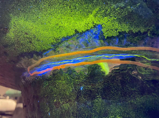
- Surface methods like Wet Fluorescent Magnetic Particle (WFMT) or Liquid Penetrant (LP) for crack detection.
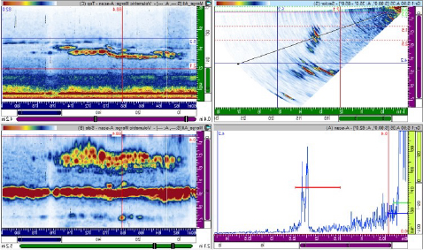
- Advanced ultrasonic techniques such as Linear Phased Array (LPA) or Time-of-Flight Diffraction (TOFD), and Focused Annular Phased Array (APA) to detect subsurface damage.
By working together early in program development, engineers and NDE specialists ensure that inspections are both targeted and efficient—focusing on high-risk areas while minimizing unnecessary examinations.
What Can Go Wrong WHEN MISALIGNED?
When engineering and NDE are not fully aligned during program development, it can lead to:
Missed Damage Due to Incorrect NDE Techniques/Instructions
- If engineering input is incorrect or missing, inspections may focus on the wrong damage mechanisms, leading to undetected flaws that could worsen over time.
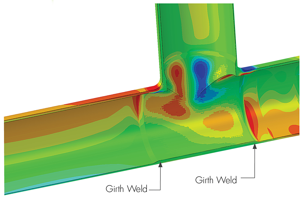
- Example: For instance, a recent industry-wide issue has been found in Tee fittings that are insufficiently reinforced to handle long-term pressure stress and have failued in the crotch areas. Without an understanding of the damage mechanism including locations in which it manifests, a technician would typically only inspect the associated girth welds rather than doing a complete evaluation of the tee crotch area including the base metal to detect subsurface cracking between the girth welds.
Unnecessary Inspections That Waste Time and Resources
- A lack of engineering guidance can result in the inspection of locations which are less consequential or likely to fail. An optimized scope will provide the best value with respect to inspection budget leading to a safer operating environment.
- Example: SI has been involved with numerous cases where “random” inspection programs without the aid of stress analysis and subsequent life calculations were either not aggresive enough or not targeted to the locations with highest likelihood of failure. While welds throughout the systems were being inspected, they were not the welds with highest likelihood of failure or associated with known industry issues – as found through analysis after the incidents occured, unfortunately.
Field Inspections
Field inspections represent the hands-on element of HEP programs, ensuring that damage mechanisms are properly identified and evaluated. This process consists of four key phases—Detection, Quantification, Classification, and Documentation—each requiring engineering involvement to ensure accuracy and to make results actionable.
Detection
Detection is the foundation of any field inspection. Success depends on selecting the correct NDE technique, as informed by engineering expertise, and the technician’s expertise in flaw detection. For example, WFMT is ideal for surface-breaking flaws, while LPA excels at identifying subsurface or ID-connected cracks. Without proper alignment between engineering predictions and NDE execution, critical flaws may go undetected.
Quantification
Quantification ensures that flaw characteristics—such as location, size, and orientation—are precisely recorded. This information is critical for determining the severity of flaws and supporting accurate fitness-for-service (FFS) evaluations. Example characteristics include:
- Is the indication located on the OD, ID, or mid-wall (subsurface)?
- Is the indication located in the base metal, heat-affected zone, or weld metal?
- What is the profile of the indication (axial or circumferential length, through-wall extent, etc.)
Even minor quantification errors can lead to unnecessary repairs or missed critical damage. Engineering oversight helps ensure precision and reduces the risk of overestimating or underestimating flaw severity.
Classification
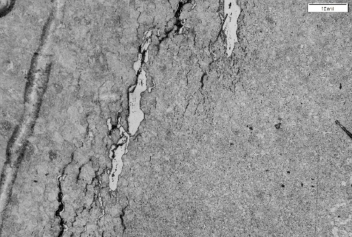
Flaw classification is the most complex phase of field inspections, requiring advanced NDE knowledge, engineering expertise, and in many cases, a metallurgical assessment of a core or boat sample. The goal is to determine whether an indication is fabrication related (e.g., slag, lack of fusion, etc.) or service-related (e.g., creep, fatigue, etc.). This distinction is absolutely critical – two flaws of the same size can have vastly different consequences depending on their origin.
To refine classification, additional or augmented methods may be used to confirm findings. For example:
- Surface replication allows metallurgical analysis of a microstructure at the tip of a crack if it is at the outer surface, confirming whether the damage is creep-related or due to another mechanism.
- In cases where flaws are evaluated over time with two or more inspections, ultrasonic testing is used to quantify subsurface flaws, helping to determine whether a crack is propagating and at what rate.
- In cases of subsurface flaws, metallurgical assessment of a core or boat sample is often required to definitively classify a flaw origin.
Accurate classification of complex flaws requires an understanding of many factors, including probe selection, technique limitations, data processing/imaging, metallurgy, and damage morphology. Often this is best accomplished with the NDE technician and engineer sitting side-by-side.
Once a flaw is confirmed as service-related, engineering unput is often required to ascribe the specific degradation mechanism. For example, creep damage occurs due to long-term exposure to high-temperature stress, whereas fatigue cracking results from cyclic loading (e.g., starts/stops). While both indications may appear similar, their progression rates and repair priorities differ significantly.
Documentation
Documentation is the final phase—and possibly the most critical. Clear, high-quality records ensure that inspection findings are properly communicated to guide future reinspection intervals and be used to adjust program assumptions as necessary. Poor documentation can lead to lost historical data, making it difficult to track flaw progression over time. Engineering involvement helps ensure that reports capture not only inspection results but also actionable recommendations for repair, continued operation with reinspection, or further evaluation.
What Can Go Wrong IN THE INSPECTION PROCESS?
There are several critical steps to the inspection process. Mishaps in any one of the steps can lead to serious consequences.
Missed Flaws Due to Inconsistent NDE Execution
- If NDE instructions are vague, misinterpreted, or poorly executed, critical flaws may go undetected.
Inaccurate Flaw Size Leading to Incorrect Engineering Assessments
- Poor quantification can lead to dangerously unconservative Fitness-for-Service determinations or overly-conservative and expensive repairs/replacements.
Incorrect Classification Misses Critical Service-Related Damage or Causes Unnecessary Repairs
- Misidentifying a service-related as fabrication-related dlaw can lead to unmonitored damage progression and failure.
Poor Documentation Leads to Loss of Inspection History
- Lack of detailed records makes it difficult to track flaw growth over time, leading to incorrect reinspection intervals or misjudged repair priorities.
Engineering Serviceability Assessments
When inspections identify flaws, degradation, or unexpected damage, the next step is to determine whether the affected component can continue operating safely or requires repair or replacement. This evaluation is driven by engineering serviceability assessments, where advanced analysis techniques are used to quantify risk, predict failure potential, and guide operational decision-making.

Fitness-for-service (FFS) evaluations, performed in accordance with API 579 / ASME FFS-1, play a critical role in this process. These assessments involve:
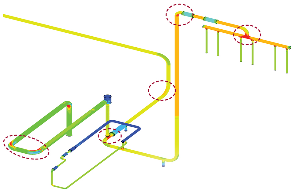
- Stress analysis: evaluating operating stresses, thermal gradients, and residual stress effects.
- Fracture mechanics: determining whether detected cracks are stable or at risk of propagation, and at what rate.
- Creep life assessments: predicting localized degradation in materials exposed to high temperatures.
- Metallurgical analysis: confirming damage mechanisms and material embrittlement.
Many of these assessments require detailed finite element analysis (FEA) to model stress distributions and crack growth across a range of operating conditions. SI engineers specialize in developing detailed models that accurately characterize field conditions and provide precise inputs to remaining life calculations. Their practical experience with field configurations and inspection methodologies helps streamline analyses, enabling faster development of actionable conclusions for plant operators.
Continuous Program Optimization
A well-designed HEP program is not static—it must evolve based on inspection findings, operational conditions, and emerging degradation trends. Continuous collaboration between engineering and NDE teams ensures that inspection strategies remain data-driven, risk-informed, and aligned with long-term reliability goals.
Inspection results and engineering assessments must feed back into the HEP program to refine reinspection intervals, update risk models, and optimize NDE methodologies. Without a structured approach to cataloging and analyzing inspection data, valuable insights can be lost—leading to inefficient inspections or missed opportunities for proactive maintenance. SI’s PlantTrack™ software provides a centralized platform for storing, visualizing, and analyzing HEP inspection data—ensuring that past findings directly inform future asset management decisions. By leveraging PlantTrack™, operator staff and SI’s engineering and NDE teams can maintain seamless integration for optimized HEP asset management.
Advancements in predictive analytics and real-time monitoring are set to fundamentally transform HEP program management, shifting from a reactive approach to a truly predictive asset management strategy. As these technologies continue to evolve, their integration with traditional inspection and engineering methodologies will be key to maximizing plant reliability and extending the life of critical piping systems. In the forthcoming Part-2 of this article, we will explore SI’s latest advancements in these areas, including digital twins, machine learning applications, and online condition monitoring.
Bringing It All Together: A Real-Word Example of Integrated HEP Program Success
When a 1,300 MW conventional boiler plant discovered a small failure in a longitudinal seam weld on its Reheat Steam line, the operator was concerned about the potential for more widespread damage. SI was engaged to perform a comprehensive inspection and engineering assessment to evaluate system integrity and prevent future failures.
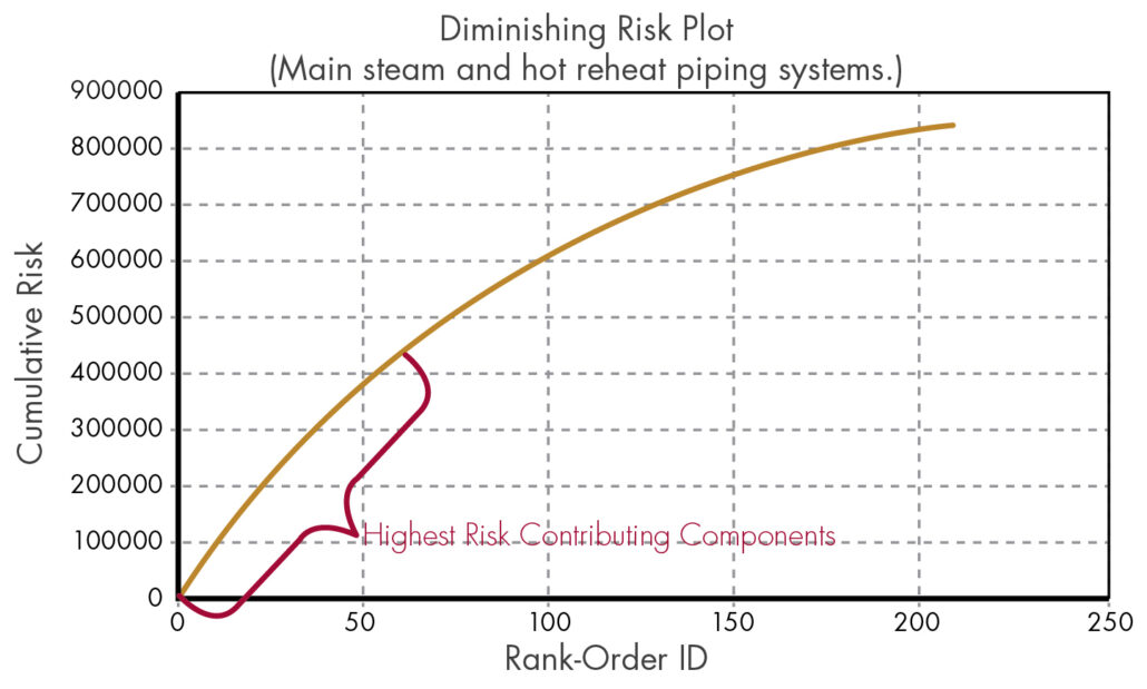
The initial directive from the operator was to inspect 2/3 of the existing system. SI’s engineering and NDE teams collaborated to develop a risk-based inspection plan, prioritizing high-risk locations to maximize impact. This risk-informed strategy was intended to maximize efficiency while ensuring no critical damage was overlooked. The resulting original work scope included:
- 1,069 feet of longitudinal seam welds.
- 115 girth welds.
SI deployed a multidisciplinary team, ensuring real-time collaboration between engineers and NDE specialists. The onsite inspections included:
- WFMT on all girth welds, longitudinal seam welds, and attachments, for detection of surface flaws.
- Fully encoded LPA UT (girth welds) and TOFD and Focused APA (seam welds) for detection of subsurface flaws.
- Metallurgical replications to confirm damage mechanisms.
- Dimensional measurements and laser profilometry for accurate component characterization.
The initial inspection findings included:
- Cracking in five additional seam welds.
- Welds fabricated with improper materials.
Based on these findings, SI recommended expanding the inspection scope and making real-time adjustments to the plan. As a result, the final inspection tally included:
- 1,375 feet of longitudinal seam welds (191 total).
- 160 girth welds.
- 15 saddle welds and 157 attachment welds.
The entire field inspection effort was completed in less than one month. In parallel, SI’s engineering team provided real-time fitness-for-service (FFS) evaluations, ensuring inspection data directly informed run-repair-replace-reinspect decisions. Destructive testing on extracted weld samples further validated material conditions and long-term risks.
The results of the effort provided the operator with a roadmap for future inspections, ensuring:
- Optimized reinspection intervals based on actual degradation rates.
- Risk-based monitoring and maintenance strategies to prevent future failures while aligning with operational goals.
By aligning engineering expertise with advanced NDE methodologies, the plant operator identified and resolved immediate safety concerns while implementing a proactive approach to future HEP asset management.
DOWNLOAD FULL ISSUE