By: Curtis Strauss and Isaac Hall
SI was engaged to design, install, and commission a site-wide impressed current cathodic protection (ICCP) system for the Turkey Point Nuclear Generating Station (PTN) to meet the site’s ongoing subsequent license renewal (SLR) commitments. Prior to its SLR application, PTN did not have a cathodic protection (CP) system for buried piping; designing and installing an all-new ICCP system at this legacy facility posed unique challenges and required more support than a typical refurbishment project. This article summarizes the site-specific requirements, challenges and adjustments made by SI as part of our project methodology, which resulted in the first large-scale CP implementation for a nuclear site pursuing SLR.
Cathodic protection is an electrochemical technique used to prevent corrosion in buried or submerged metal structures [1], such as pipelines and storage tanks. It works by applying an electrical current to shift the metal’s potential (voltage) relative to its soil environment, effectively halting corrosion. While CP is widely used, its application in dense station environments (such as nuclear power plants) is complicated by the network of interconnected metallic systems, grounding grids, and safety-related piping. These factors create electrical discontinuities and interfere with current distribution, requiring a tailored, iterative approach to ensure effective protection.
Regulatory Basis for CP in Nuclear Plants
Guidelines for applying CP for the protection of buried piping in nuclear plants are outlined in the NRC’s GALL-SLR report [2], specifically within Aging Management Program (AMP) XI.M41. This program defines preventive measures to mitigate external corrosion and establishes criteria for evaluating CP system effectiveness. The primary criterion requires achieving a polarized potential of -850 mV relative to a copper/copper sulfate electrode (CSE), measured using an “instant-off” technique to eliminate IR drop error [3].
While the -850 mV threshold is widely used, it can be impractical in complex plant environments due to factors such as high soil resistivity and extensive buried infrastructure. The GALL-SLR allows for alternative criteria – such as demonstrating at least 100 mV of CP polarization – provided the program incorporates additional verification methods for the most corrosion-susceptible piping materials (see Figure 1). Corrosion rate monitoring (CRM) is one such method, providing direct, real-time data on material loss trends to validate CP effectiveness.
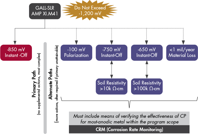
For existing sites implementing large-scale CP systems for the first time, the GALL-SLR acknowledges that achieving full compliance may require iterative design modifications and use of multiple criteria. Regardless of approach, plants must demonstrate that the system provides effective protection over time, either by meeting voltage-based criteria during periodic surveys or by confirming that corrosion rates remain within acceptable limits (e.g., via CRM). Presence of effective CP reduces the number of direct inspections, minimizing the effect to ensure aging is managed within the AMP’s regulatory framework.
Turkey Point Project Overview
In March 2021, SI was engaged by NextEra Energy (NEE) to design, install, and commission a site-wide ICCP system at the Turkey Point Nuclear Generating Station (PTN) to meet the commitments in NEE’s SLR application. PTN was the first U.S. nuclear plant to be granted an SLR license, extending its operating life to 80 years. However, prior to this project, the site lacked a CP system for buried piping, making the design and implementation of an entirely new system a significant undertaking.
The primary objective was to provide effective CP for two key buried piping systems—Fire Protection (FPS) and Intake Cooling Water (ICW)—in accordance with AMP XI.M41 requirements. However, this project posed several unique challenges, such as:
- Electrical discontinuities in the non-welded FPS piping and between buried pipe and above-ground appurtenances.
- A complex, congested network of buried metallic systems and grounding infrastructure.
- Limited access to critical piping sections, particularly for the ICW system.
- An aggressive project schedule, driven by SLR commitments.
- Rigid AMP commitments, employing the most-conservative criterion (-850 mV) without consideration of site-specific requirements.
- Geological constraints, which increased the difficulty of drilling and precluded the use of deep anode groundbeds.

To address these challenges, SI and its CP subcontractor, Bass Engineering, took an iterative approach to system design, installation, and commissioning. This process required multiple design refinements and targeted adjustments to achieve compliance with CP effectiveness criteria while navigating site-specific constraints. The following sections outline the overall CP implementation process and examine key challenges encountered at PTN, along with the solutions developed to address them.
General CP Implementation Process
SI follows a structured process for large-scale CP projects, enabling adaptation to site-specific challenges while minimizing uncertainty and maintaining schedule adherence. These phases are outlined below.
Project-Specific Challenges and Optimization
The design and installation of an ICCP system at PTN presented multiple challenges due to tight project timelines, complex site infrastructure, and unique environmental conditions. SI employed the process shown below to achieve a successful implementation, through an iterative approach that allowed for refinement throughout the design, implementation, testing, and acceptance stages.
Project Timeline and Execution Constraints
The PTN CP implementation was constrained by a strict 18-month timeline, driven by commitments made to the NRC during the Subsequent License Renewal Application (SLRA). The project schedule was particularly demanding because Turkey Point had never previously installed a CP system for its buried piping. Unlike a CP refurbishment—where existing system data can be leveraged—this required a full site assessment, design, installation, and commissioning from scratch.
To stay on schedule, SI and its partners had to prioritize design-phase activities, focusing early efforts on:
- Assessing electrical continuity in the fire protection system (FPS), which was suspected to have discontinuities.
- Planning logistics for deep anode and shallow distributed groundbeds, given space and geological constraints.
- Collecting buried piping data for modeling and system layout.
![]()
Initial Assessment and Planning
Site evaluation, environmental considerations, and corrosion risk analysis to establish project scope and key design inputs. Determination of structure or structures to be protected.
Engineering Design and Equipment Specification
Iterative phase includes initial current requirement calculations and determination of system type / configuration (e.g., galvanic vs. ICCP, distributed vs. remote). Development of system layout, selection of materials and components (e.g., anodes, rectifiers, cables, bonding locations), and approximation of current distribution. May also include evaluation of cost and feasibility.
Field Implementation
Installation of CP system infrastructure, including anode groundbeds, power feeds, connections to target structures, and CP test equipment (i.e., test stations).
Initial Testing and Evaluation
System energization, validation of electrical continuity or isolation, baseline testing, and rough balancing based on field data.
System Optimization
Refinement of system parameters and final balancing of rectifier outputs to achieve maximum performance. If initial testing identifies performance gaps, additional modifications may be required (e.g., isolation bonding, additional groundbeds, etc.).
Ongoing Maintenance and Updates
Routine system monitoring, annual CP surveys, and any program-specific testing to confirm continued effectiveness. Adjustments and corrective actions are implemented as needed.
Despite efforts to streamline the process, some design phases were compressed compared to typical CP projects. This meant that certain design inputs—such as soil resistivity and total buried surface area—were estimated rather than measured directly. These unknowns contributed to gaps in the initial design, requiring later modifications to meet system performance requirements.
Even with these challenges, SI and its partners successfully delivered the first large-scale ICCP system for an SLR-licensed plant on time. However, the accelerated timeline meant that some early assumptions had to be revisited during implementation, leading to iterative system refinements.
Complexity of Existing Infrastructure
A significant challenge in implementing CP at PTN was the highly congested underground environment. The plant’s buried infrastructure included a mix of metallic systems, grounding grids, and safety-related piping, many of which were electrically interconnected in unpredictable ways.
A critical issue was the electrical discontinuity within the FPS piping system, which used non-welded, mechanically joined ductile iron piping. These joints do not always provide reliable electrical continuity, resulting in sections of piping that were unintentionally isolated from CP protection. This posed a risk of stray current corrosion, where unprotected pipe segments could experience accelerated metal loss instead of protection.
Further complicating the design, the station’s grounding grid was assumed to be continuous across the site. However, post-installation testing revealed that grounding connections varied significantly, leading to unexpected current distribution issues. This misalignment required additional continuity bonding and negative rectifier connections to improve current return paths and prevent stray current interference.
Additionally, gaps in design input—such as undocumented fire protection piping—led to errors in estimating total CP current demand. The system was initially undersized, requiring supplemental anodes and rectifier output adjustments to compensate.
Site-Specific Installation Challenge
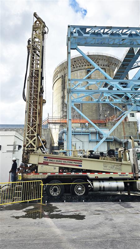
Beyond electrical complexities, the physical installation of the ICCP system was complicated by Turkey Point’s geology. The original CP design included deep anode groundbeds, but porous limestone formations created drilling difficulties that exceeded expectations.
During installation, drill crews encountered subsurface voids, which resulted in:
- Frequent drilling fluid loss, making borehole stabilization difficult.
- Equipment failures, increasing installation delays and costs.
- Higher-than-anticipated resistivity variations, affecting CP current distribution.
To mitigate these risks, SI and its partners modified the deep groundbed design, reducing borehole depth from 300 ft to 150 ft while increasing the number of anodes per groundbed. This adjustment maintained CP coverage while improving constructability.
Another major challenge was physical space limitations. The plant’s discharge side had minimal room for CP infrastructure, requiring customized rectifier placement and cable routing. In some cases, anode locations had to be shifted or replaced with alternative CP methods to accommodate space constraints.
CP System Performance and Optimization
One of the most significant project challenges was meeting the rigid acceptance criteria defined in PTN’s SLRA commitments. While the GALL permits flexibility in CP effectiveness criteria – including a 100 mV polarization shift alternative – PTN initially committed to the most conservative threshold, requiring -850 mV polarized potential at all monitored test locations.
During initial commissioning, early test results revealed that meeting this standard was not technically feasible due to:
- Higher-than-expected soil resistivity, which limited CP current flow.
- Greater-than-estimated buried metallic surface area, significantly increasing CP output demand.
- Electrical discontinuities and grounding grid separation, disrupting uniform current distribution.
To address these issues, SI and its partners implemented an iterative optimization strategy, including:
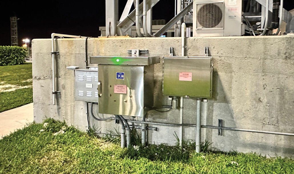
- Installing additional dedicated test stations with corrosion rate monitoring (CRM) hardware to directly measure local corrosion rates.
- Rebalancing rectifier outputs to improve current distribution.
- Installing additional continuity bonds to mitigate electrical discontinuities.
- Adding three supplemental deep anode groundbeds, increasing overall CP current capacity.
Even with these modifications, it was clear that full compliance with the -850 mV criterion was neither practical nor necessary for effective corrosion prevention. SI and NEE initiated a licensing amendment process to adopt the 100 mV polarization shift criterion, while utilizing the CRM data as an independent verification method to confirm CP effectiveness.
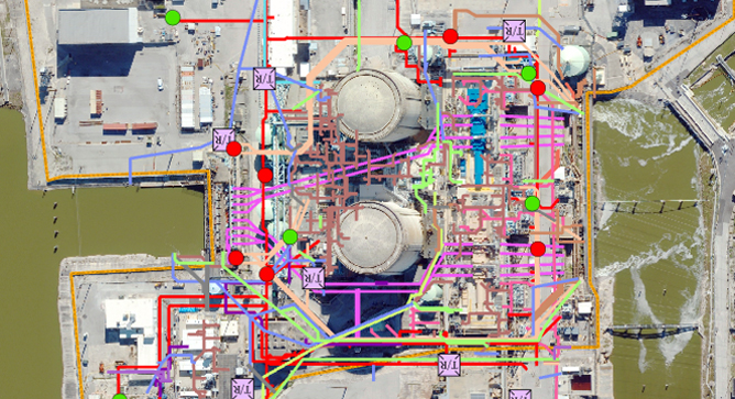
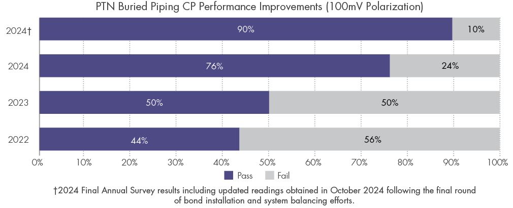
The optimization process was executed in multiple phases, beginning in late-2022 and concluding in early-2024. Throughout implementation, progress toward the 100 mV criterion was verified through site-wide “annual” CP surveys, conducted at key milestones. Figure 4 illustrates the survey results overlaid on a map of the plant and target piping systems, while Figure 5 shows the progression of system improvements at each step in the optimization process. Additionally, CRM data confirmed that actual corrosion rates were well within acceptable limits (less than 1 mil / year), further validating that the CP system provided adequate protection – even in areas where 100 mV polarization was not fully achieved.

Conclusion
The implementation of a full-scale ICCP system at PTN marked a significant milestone, both for the site and for the nuclear industry’s approach to management of aging piping under SLR. As the first U.S. nuclear plant granted an SLR license, PTN’s CP system had to be designed and implemented from the ground up, introducing challenges that ranged from electrical discontinuities and geological constraints to strict licensing commitments and a compressed project timeline.
Through an iterative approach, SI and its partners were able to navigate these challenges while refining system performance. Early assumptions—particularly regarding electrical continuity, system grounding, and total CP current demand—required ongoing adjustments, including design modifications, additional bonding, and increased CP capacity. By leveraging corrosion rate monitoring (CRM) as an alternative assessment method, the team successfully demonstrated that the system provided effective protection, even when compliance with the original -850 mV criterion was impractical.
The PTN project provides key lessons for CP implementation at other nuclear facilities, particularly for sites transitioning to long-term aging management strategies. These insights are summarized in the box below. As other plants implement SLR AMP strategies for long-term buried piping protection, the experiences gained at PTN will help guide more efficient, flexible, and technically sound CP implementation.
Key Takeaways
This project demonstrated that from-scratch, large-scale CP implementation in response to SLR-commitments requires flexibility and iteration.
- Regulatory commitments should be made with practical implementation in mind, considering alternative performance criteria where appropriate.
- Design assumptions must be verified early to avoid later rework.
- Geological constraints should be factored into deep groundbed feasibility before finalizing the design.
- Electrical continuity must be tested across all metallic systems to prevent isolation issues.
Through a structured yet adaptive approach, SI successfully delivered an effective ICCP system, balancing design compliance, site constraints, and long-term system maintainability.
References
- Luciano, Lazzari and Pietro, Pedeferri. Cathodic Protection. Milan : Polipress, 2006.
- NRC. NUREG-2191 Generic Aging Lessons Learned for Subsequent License Renewal (GALL_SLR) Vol. II. Washington, D.C. : U.S. Nuclear Regulatory Commission, 2017.
- SP0169 Control of External Corrosion on Underground or Submerged Metallic Piping Systems. Houston : NACE International, 2013.