
News & Views, Volume 44 | Metallurgical Lab Featured Damage Mechanism – Long-Term Overheating/Creep (LTOC) in Steam-Cooled Boiler Tubes
By: Terry Totemeier
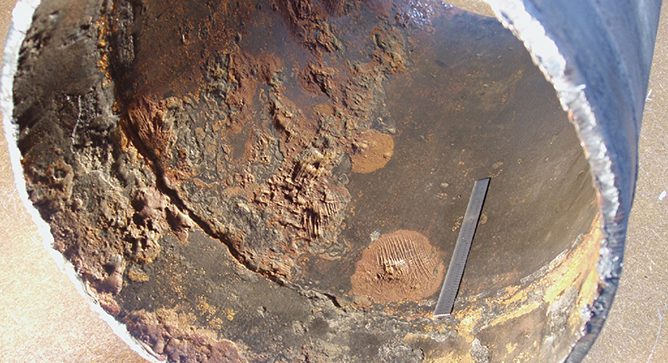
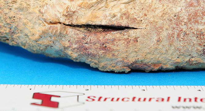 Long-term overheating and creep damage are often the damage mechanisms associated with the normal or expected end of life of steam-touched tubes, generally occurring after 100,000 hours or more of service life at elevated temperatures and pressures. Long-term overheating and creep can also occur when the rate or accumulation of creep damage is moderately higher than anticipated by original design. There are a number of possible reasons for this, but in general the problem can be attributed to one of the following: a non-conservative original design, higher-than-anticipated heat absorption, lower-than-anticipated steam flow, or wall loss caused by external wastage.
Mechanism
The mechanism of failure for LTOC is simply the accelerated accumulation of creep damage in the component over a span of time that is well short of the anticipated design life, but sufficiently long that creep is the dominant damage mode. This damage is typically associated with the operation of the tube above the oxidation limit for the material involved. This has two effects, which both contribute to long-term creep failure: reduction in wall thickness due to oxidation loss, and build-up of oxide on the tube internal surface, which insulates the tube from the cooling effect of the steam, leading to increasing tube metal temperatures over time.
 A March 16, 2017, advisory bulletin (Docket No. PHMSA-2016-0131 – “Pipeline Safety: Deactivation of Threats”) gave guidance on the deactivation of pipeline threats, including the threat of internal corrosion.
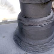
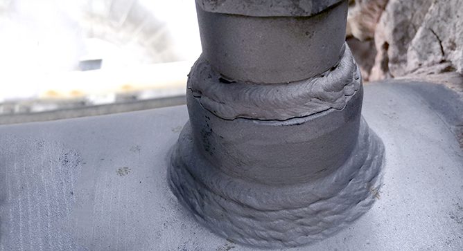 A dissimilar metal weld (DMW) is created whenever alloys with substantially different chemical compositions are welded together – for example, when a low-alloy steel such as Grade 22 (2¼ Cr-1Mo) is welded to an austenitic stainless steel such as TP304H (18Cr-8Ni).
 Nuclear plant workers accrue most of their radiation exposure during refueling outages, when many plant systems are opened for corrective and preventive maintenance. The total refueling outage radiation exposure can be 100-200 person-Rem at a typical Boiling Water Reactor (BWR), and 30-100 person-Rem at a typical Pressurized Water Reactor (PWR). Accrued refueling outage radiation exposure values can be significantly greater than these values depending upon radiation fields, outage work scope, and emergent work. Outage radiation exposure is one metric used by a plant to determine outage success and by industry regulators in assessing the overall performance of a plant. Plants with high personnel radiation exposure tend to be those plants with more equipment problems and more unscheduled shutdowns; consequently, they may be subjected to increased regulatory oversight.
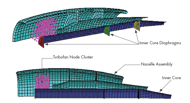
 Things change, that’s just a fact of life. But when it comes to engineering codes and standards, change can be confusing, frustrating and expensive. As it relates to seismic design and certification of equipment, it is beneficial to understand the impact of code changes early to begin incorporating requirements in new equipment design, product updates and in the certification process.
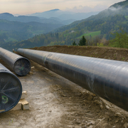
 Structural Integrity
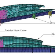
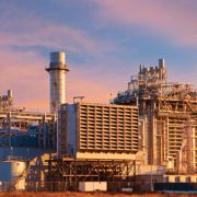
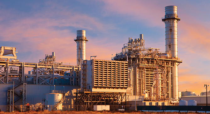 Attemperators (aka desuperheaters) are used in fossil and combined cycle plants to protect boiler/HRSG components and steam turbines from temperature transients that occur during startup or load changes. The attemperator sprays water droplets into the superheated steam to ensure that the downstream, mixed, steam temperature will not adversely affect downstream components.