Structural Integrity Associates Achieves Milestone with Pegasus Code Development

Structural Integrity Associates Achieves Milestone with Pegasus Code Development

Structural Integrity Associates | Structural Integrity Associates Achieves Milestone with Pegasus Code Development

Structural Integrity Associates | Structural Integrity Associates Achieves Milestone with Pegasus Code Development
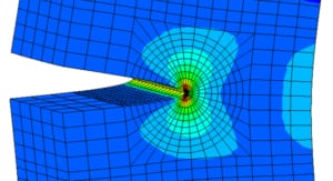
On October 28th, the Structural Integrity (SI) Nuclear Fuel Technology Team achieved a major milestone in completing the first Verification & Validation phase in the development of its nuclear fuel performance and behavior code Pegasus©.  “This is a significant step by the SI Team” commented Vick Nazareth, SI Fuel Director.  “We have been developing Pegasus© since 2017 to incorporate cutting edge computational technology and four decades of fuel behavior modeling and analysis expertise into a software program”.  The code addresses a need for deeper fuel integrity insights within the nuclear industry to achieve next level fuel performance and licensing.  Dr. Joe Rashid, Scientist and Senior Technology Developer of the code added “this code will analyze fuel behavior through the entire fuel cycle from initial startup to used-fuel storage”.

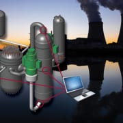
SI announced the development of Pegasus© in the SI newsletter in 2019, Introducing Pegasus: State-of-the-Art Nuclear Fuel Behavior with the objective of enhancing the fidelity of fuel behavior and performance in support of advanced fuel technologies.  The Pegasus© code will go through additional validation testing over the next several months to meet a production roll-out in early 2021 in support of fuel performance behavior analysis across a broad spectrum of light water reactor and advanced reactor fuel designs.

” I am proud of the SI Fuel Team”, said Mark Marano, SI CEO.” This milestone exemplifies our ability to provide innovative structural integrity solutions for clients across structures, systems, components, water chemistry and nuclear fuel.”

Structural Integrity is an employee-owned specia­­lty engineering and services company providing innovative engineering solutions and services to achieve asset management excellence across multiple industries including Nuclear, Fossil, Oil & Gas, Renewables, and Critical Infrastructure.

Executive Director of Project Management Nuclear Business Development Leader

Executive Director of Project Management Nuclear Business Development Leader

Structural Integrity Associates | Mike Battaglia

Mike comes to SI following tenures at Westinghouse Electric and Framatome. During his 25 year career in the nuclear industry, Mike has held a variety of leadership roles that spanned operations and business development. Selected accomplishments in the operations realm during that time included building and leading the Westinghouse Balance of Plant Engineering Department that included over 100 engineers, and leading the commercial deployment of a new alloy 600 mitigation technology in the US. From a commercial standpoint, Mike led the Business Development Departments for two different 75+ Million dollar businesses to achieve substantial top-line growth.

Mike will bring the broad range of experiences to SI to drive improvement in project management in order to achieve next-level performance and customer satisfaction. Mike will also hold a secondary role of Business Development in the SI Nuclear Business Unit, where he will use his experience and industry contacts to promote SI engineering technology to the global fleet.

News & View, Volume 48 | Increase in Reinspection Intervals for BWR Reactor Internals

News & Views, Volume 48 | Increase in Reinspection Intervals for BWR Reactor Internals

By:  Dick Mattson and Minghao QinNews & View, Volume 48 | Increase in Reinspection Intervals for BWR Reactor Internals

A U.S. BWR utility contracted with Structural Integrity (SI) to review their current reinspection guidance documents relative to those contained in the BWRVIP inspection guidelines, the purpose of which was two-fold:

  1. ­Are current reinspection guidelines compliant with industry requirements?
  2. ­Are there components where reinspection intervals could possibly be extended?

READ MORE

News & View, Volume 48 | Acoustic Resonance

News & Views, Volume 48 | Acoustic Resonance

By: Mark Jaeger and Andrew CromptonNews & View, Volume 48 | Acoustic Resonance

Acoustic resonance is a phenomenon in which an acoustic system amplifies sound waves whose frequency matches one of its own natural frequencies of vibration (its resonance frequencies).

in everyday life.  In the most simple at home example, blowing air over the open end of a bottle.  Blow too hard, nothing. Blow too soft, nothing.  When done just right, the bottle produces a sound (audible vibration).  Just like that, you have acoustic resonance.  Every wind instrument in a band uses acoustic cavity resonance to produce music.  Take a piece of flexible hose, spin it in the air until it whistles, again, acoustic resonance.  When an acoustic cavity resonance happens inside piping systems, especially those with high energy flow, those seemingly harmless vibrations we illustrated above can cause serious damage.  This phenomena can occur in nearly any industry, sometimes with benign consequences and other times with catastrophic results.


News & View, Volume 48 | Plant Materials Aging and Degradation

News & Views, Volume 48 | Plant Materials Aging and Degradation – Nuclear IGSCC Mitigation Optimization and Equipment Advances

By:  Erica Libra-Sharkey

INDUSTRY CHALLENGE

News & View, Volume 48 | Plant Materials Aging and Degradation

From the US Department of Energy, Office of Nuclear Energy, “The demanding environments of an operating nuclear reactor may impact the ability of a broad range of materials to perform their intended function over extended service periods. Routine surveillance and repair/replacement activities can mitigate the impact of this degradation; however, failures still occur. With reactors being licensed to operate for periods up to 60 years, with further extensions under consideration, and power uprates being planned, many of the plant systems, structures, and components will be expected to tolerate more demanding environments for longer periods. The longer plant operating lifetimes may increase the susceptibility of different systems, structures, and components to degradation and may introduce new degradation modes.

While all components potentially can be replaced, decisions to simply replace components may not be practical or the most economically favorable option. Therefore, understanding, controlling, and mitigating materials degradation processes and establishing a sound technical basis for long-range planning of necessary replacements are key priorities for extended nuclear power plant operations and power uprate considerations. https://www.energy.gov/ne/materials-aging-and-degradation.

READ MORE

News & View, Volume 48 | Fatigue Adjustment Factors for Increased Cyclic Life

News & Views, Volume 48 | Fatigue Adjustment Factors for Increased Cyclic Life

By:  Bill WeitzeNews & View, Volume 48 | Fatigue Adjustment Factors for Increased Cyclic Life

100% of thermal stress was treated as nonlinear gradient stress and linear bending stress was about 12% of the moment stress. Structural Integrity’s (SI’s) review of the stress terms used in piping analysis show that pressure stress does create bending stress in components…

EPRI Report 3002014121 “Development of Fatigue Usage Life and Gradient Factors” has developed fatigue usage adjustment factors that account for: 1) increased cyclic life associated with the growth of potential engineering size fatigue cracks in thicker components (thickness factor, TF; also called life factor, LF), and 2) the presence of through-thickness stress gradients (gradient factor, GF). (TF is used in the issued Code Case.)  These factors are applied to cumulative usage factor, U, in air.

READ MORE

News & View, Volume 48 | Examination Optimization for PWR and BWR Components

News & Views, Volume 48 | Examination Optimization for PWR and BWR Components

By:  Scott Chesworth, Bob Grizzi, and Dilip Dedhia

Optimizing the inspection interval for high-reliability components whose examinations have a significant outage impact.News & View, Volume 48 | Examination Optimization for PWR and BWR Components

Welds and similar components in nuclear power plants are subject to periodic examination under ASME Code, Section XI.  Typically, examinations are performed during every ten-year inspection interval using volumetric examination techniques, or a combination of volumetric and surface examination techniques.  Nuclear plants worldwide have performed numerous such inspections over the plant history with few service induced flaws identified.  Since personnel health and safety, radiation exposure, and overall outage costs associated with these inspections can be significant, Structural Integrity (SI) was contracted by the Electric Power Research Institute (EPRI) to review the technical bases for the inspection intervals for select components.  The goal was to determine whether the frequency of current inspection requirements was justified or could be optimized (i.e., reduced in order to devote more attention to higher-value inspections and thereby maximize overall plant safety).  Special priority was given to components demonstrating an exceptional history of reliability and whose examinations have a significant outage impact.

News & Views, Volume 48 | Environmentally-Assisted Fatigue Screening and Managing EAF Effects in Class 1 Reactor Coolant Components

News & Views, Volume 48 | Environmentally-Assisted Fatigue – Screening and Managing EAF Effects in Class 1 Reactor Coolant Components

By: Dave Gerber and Terry HerrmannNews & Views, Volume 48 | Environmentally-Assisted Fatigue Screening and Managing EAF Effects in Class 1 Reactor Coolant Components

Environmentally-Assisted Fatigue (EAF) screening is used to systematically identify limiting locations for managing EAF effects on Class 1 reactor coolant pressure boundary components wetted by primary coolant.  This article provides an overview of the methods developed and used by Structural Integrity (SI) for Class 1 components having explicit fatigue analyses performed using ANSI/ASME B31.7(1) and ASME Section III(2).  A future article will discuss how this is performed for Class 1 piping designed and analyzed to ASME/ANSI B31.1(3).

READ MORE

News & View, Volume 48 | SI-FatiguePro Version 4.0 Crack Growth Module Application Case Study; Complex Multi-Cycle Nuclear Transients

News & Views, Volume 48 | SI:FatiguePro Version 4.0 Crack Growth Module – Application Case Study Complex Multi-Cycle Nuclear Transients

News & View, Volume 48 | SI-FatiguePro Version 4.0 Crack Growth Module Application Case Study; Complex Multi-Cycle Nuclear Transients

By: Curt Carney

As plants enter their initial or subsequent license renewal period one of the requirements is to show that fatigue (including environmental effects) is adequately managed.  For some locations in pressurized water reactors (PWRs), it can be difficult to demonstrate an environmental fatigue usage factor less than the code allowable value of 1.0.  Therefore, plants are increasingly turning to flaw tolerance evaluations using the rules of the ASME Code, Section XI, Appendix L.  Appendix L analytically determines an inspection interval based on the time it takes for a postulated flaw (axial or circumferential) to grow to the allowable flaw size.  For surge line locations, this evaluation can be very complex, as the crack growth assessment must consider many loadings, such as: insurge/outsurge effects, thermal stratification in the horizontal section of the line, thermal expansion of the piping (including anchor movements), and internal pressure.  Trying to envelope all of these loads using traditional tools can lead to excess conservatism in the evaluation, and short inspection intervals that reduce the value of an Appendix L evaluation.

News & Views, Volume 48 | Metallurgical Lab Case Study – Grade 91 Elbows Cracked Before Installation

By:  Wendy Weiss and Terry Totemeier

News & View, Volume 48 | Metallurgical Lab Case Study - Grade 91 Elbows Cracked Before InstallationStructural Integrity (SI) personnel visited a power plant construction site to examine four Grade 91 elbows (ASTM A234-WP91 20-inch OD Sch. 60) that were found to contain axially oriented surface indications. The elbows had not yet been installed. The indications were initially noticed during magnetic particle testing (MT) after one end of an elbow was field welded to a straight section and post weld heat treated (PWHT). Subsequently, three additional similarly welded elbows were inspected and indications were found at both the welded (inlet) and open (outlet) ends of three elbows. The elbow with the most significant indications was selected for SI’s on-site examinations. Figure 1 shows the inlet and outlet ends of the selected elbow.

READ MORE