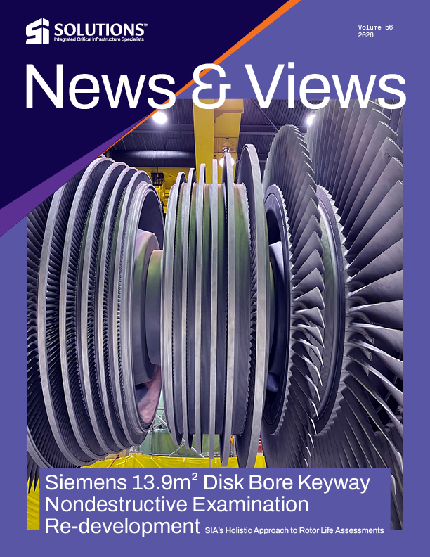
SIA’s Holistic Approach to Rotor Life Assessments
Structural Integrity Associates validated automated PAUT to achieve 100% disk bore/keyway coverage on Siemens 13.9 m² rotors—within a predictable five-day outage—supporting defensible life assessments without de-stacking.
By: David Dechene and Nick Dechene
INTRODUCTION
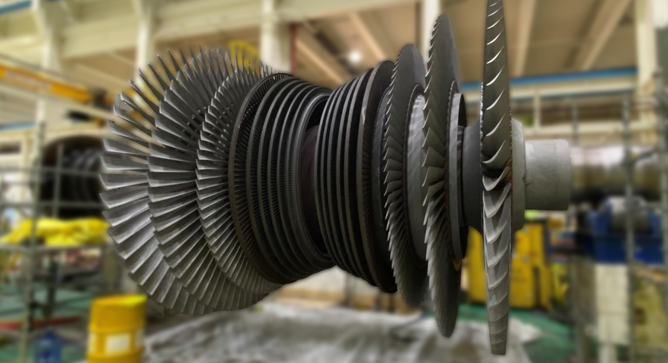
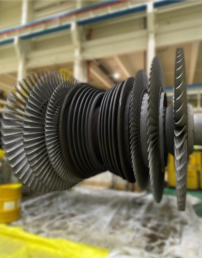
The Siemens retrofit 13.9 m² rotor is a 1,800 RPM double-flow, low-pressure (DFLP) turbine rotor commonly used by nuclear utilities for power generation. This rotor is a built-up design, meaning it has a shaft with three shrunk-on wheels (or disks) per flow (at each end).
Like its disk-rim blade attachments, the shrunk-on disk-bore/keyway regions on 13.9m² rotors are susceptible to intergranular stress corrosion cracking (IGSCC). This is due to high-stress concentrations inherent with the specific geometry and steam cycle chemistry. Poor water chemistry or fabrication-type discontinuities introduced during rotor assembly cause pits. These pits can facilitate the initiation of cracks during the unit’s operation. Nondestructive examinations of the rotor should include the complete rotor periphery (Steampath), L-0 stage blade roots, disk rim blade attachments, and shrunk-on disk bore/keyways, using appropriate examination techniques.
The shrunk-on disk bores are a key component in assessing a rotor’s viability for continued operation. A thorough evaluation of that region must be performed using a suitable inspection technique that most accurately detects and characterizes in-service damage in the bore region. Without disassembly of the rotor, the only viable way to interrogate the disk ID and keyway surfaces is by using an ultrasonic method. An automated phased array UT (PAUT) ultrasonic technique allows for post analysis and peer review of the data and is an industry best-practice endorsed by EPRI.
Despite being the right technique, performing PAUT inspections of the disk bore region does come with inherent limitations. These limitations may include managing complex, uneven surface geometries, including minor geometric variations between rotors that often arise. Attenuation of the ultrasonic sound beam due to long travel distances (sound-path) is also a concern, as are potentially minor variations in material properties. These limitations combined make achieving 100 percent coverage at the disk-bore region challenging. However, without 100 percent coverage, the inspection provides limited data, reducing the NDE information available to support an engineering rotor life assessment. Recognizing this challenge, Structural Integrity Associates (SIA) proactively undertook a redevelopment of its disk bore inspection protocol in 2023, with the specific goal of achieving 100 percent examination coverage across all six disk bore regions on Siemens 13.9 m² rotors.
The task at hand was 1) to develop an inspection protocol that would ensure 100 percent coverage of all six disk bores without compromising sensitivity, despite minor variations between rotors, and 2) to build proven contingency options to address one-off situations like local geometric variations or attenuation issues that inevitably arise.
TECHNIQUE DEVELOPMENT
To detect discontinuities propagating from the disk bore and keyway regions, an automated PAUT technique is employed. Demonstrated multi-element search units are directed at the normal angle to the bore, enabling detection of radial-axially oriented cracks at the bore surface and keyways.
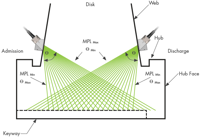
Figure 1. Turbine disk web scan nomenclature (Side View)
SIA started by developing detailed CAD models of the rotor, including the shaft and disks. Using CIVA advanced ultrasonic modeling software, they began the arduous process of evaluating numerous probe wedge combinations, even trialing theoretical probes. Keeping in mind component geometry, material properties, and sound-path distances, they set out to determine the best combination of ultrasonic coverage, inspection sensitivity, flaw detection capability, and interpretation of results for each of the three disks per flow.
Beam plots were used to determine how the ultrasonic coverage would be achieved. This was followed by beam computations to show the resulting ultrasonic field for every combination of probe and focal laws. These modelling tools enabled SIA to compare probe parameters such as frequency, element size, wedge angle, focal laws, etc., on numerous probe/wedge/placement combinations. After determining the theoretical best options, simulations were then modelled to validate results and determine flaw size detectability.
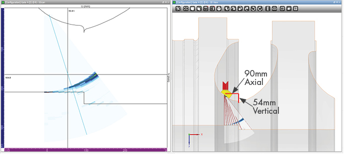
Figure 2. Example of detail in probe placement for optimal detection
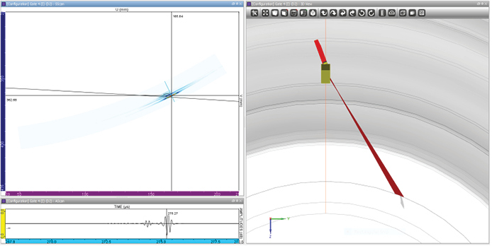
Figure 3. Example of detection capability on a 3mm x 6mm elliptical flaw
Disk-specific probe placements were calculated, trialed, and validated for each probe, at each disk and hub surface. Also, contoured wedges were designed and modeled to allow for multiple scan directions at each specific inspection location.
Next, simulated flaws were embedded in the models to determine ultrasonic responses. The desired and resultant detection capability was to distinguish a 3mm x 6mm elliptical flaw at the center of the disk, with detection improving as the flaw approached the ends of the disk.
THE RESULTING PROTOCOL
Following months of modelling, scan simulations, and iterative adjustments, SIA’s redesigned disk bore inspection protocol used a series of customized probe/wedge combinations placed at optimized locations unique to each disk. Using multiple wedges, the beam was aimed in three directions at each location: normal to the bore surface, tangential to the bore surface clockwise, and tangential to the bore surface counterclockwise.
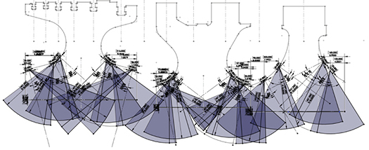
Figure 4. side view showing probe placement and coverage overlap for all three wheels per flow
To ensure full coverage with overlap, this new protocol requires a minimum of 17 unique probe placements, collecting at least 51 360° scans per flow, or 102 scans per rotor. Additional scans will be collected as needed to account for local variances. This redeveloped protocol ensured 100 percent coverage of all six disk-bore surfaces. By capitalizing on well-thought-out probe placement locations and angles, overlapping coverage across all high-stress regions was achieved. In the event of attenuation issues, a large-aperture, large-footprint probe designed to punch through attenuative or geometrically challenging materials was designed, tested, and implemented as a contingency plan.
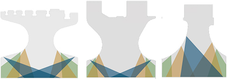
Figure 5. cleaned up graphic of Figure 4 highlighting coverage and overlap
The redeveloped protocol was then subjected to rigorous in-house validation exercises using calibration blocks, culminating with an eventual field trial to confirm results.
A summary of the advantages of the re-developed disk bore region PAUT protocol includes:
- 100 percent coverage with overlap/redundancy in high-stress regions
- Custom primary probes with larger near-fields, increasing coverage and reducing risk of attenuation losses
- Three wedges per location; cut to specific radii to optimize component contact
- A flat wedge to establish ID roll to determine coverage and to identify laminations in the part
- Pre-determined squint-angle wedges to optimize the reflective signals looking clockwise and counter-clockwise
- Contingencies in place to address attenuation and geometric variation risks
Detailed post-processing procedures have been established for the automated PAUT data to further aid in the detection of service damage resulting from IGSCC. To date, this redeveloped inspection protocol has been successfully used to inspect three Siemens 13.9 m² rotors at two nuclear facilities for two separate utilities.
SUMMARY
SIA provides comprehensive NDE and engineering assessments for the Siemens 13.9 m² DFLP rotor, including a recently validated, redeveloped PAUT protocol. This rotor’s disk bore/keyway regions have historically faced IGSCC risk and challenging inspection geometry. To address this, SIA led a collaborative internal effort — bringing together Engineers, senior NDE technicians, and Applications Development support — to reinvent the inspection approach from the ground up.
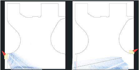
Figure 6. Screen shots of actual data with disk overlay showing coverage
The result is a new automated PAUT protocol that delivers 100 percent disk bore coverage with overlap and redundancy in high-stress areas, using optimized probe/wedge placements and validated focal laws. The protocol was modeled, simulated, and trialed in the field within a predictable, approximately five-day, two-shift outage window, and supports a defensible basis for rotor life assessments without de-stacking.
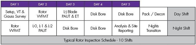
Figure 7. Typical inspection schedule
SIEMENS 13.9m² OFFERING – A HOLISTIC APPROACH
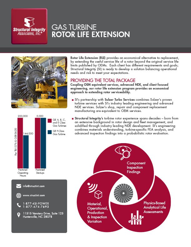
Structural Integrity Associates provides comprehensive, fully integrated solutions for life assessment, inspection, failure analysis, and online monitoring of gas turbines, steam turbines, and generator equipment. Their holistic approach ranges from proactive management plans to emergent analysis and inspections. They offer unprecedented value by maximizing the life of existing assets in a safe, risk-informed manner.
Non-destructive Evaluation
For the 13.9m² DFLP rotor as a whole, the following nondestructive examinations are recommended to ensure appropriate coverage of the rotor periphery, L-0 blade roots, disk rim blade attachments, and shrunk-on disk-bores/keyways:
- Visual examination of the entire rotor periphery
- Wet fluorescent magnetic particle testing (WFMT) examination of the rotor steam path (L-0 through L-2 blades) and foil-hardened wear surfaces (L-0 blades)
- Manual phased array ultrasonic (PAUT) examination of the curved axial-entry L-0 stage blade roots
- Automated PAUT examination of the shrunk-on disk-bores/keyways for all three disks on both ends of the rotor
- Automated PAUT examination of the L-0, L-1, and L-2 stage axial entry disk rim blade attachments
With a six-person, two-shift crew, the complete NDE protocol—including setup, inspection, and data analysis—can be completed in approximately 10 shifts (five calendar days), minimizing outage duration and avoiding the added cost of de-blading.
Engineering Assessment
When indications are identified via NDE, the remaining service life of the rotor can be assessed using deterministic and probabilistic fracture mechanics to determine the likelihood of failure within a given operational envelope. Engineering analyses are used to assess life-limiting conditions, such as susceptibility and failure-consequence factors, and future operating expectations to derive a suitable inspection plan.
Learn more about SIA’s extensive expertise and experience with rotor inspections on our turbine and generator page, or contact us today.
DOWNLOAD FULL ISSUE