By: John Molloy and Dave King
This article summarizes SIA’s independent root cause analysis of a catastrophic steam turbine failure at a coal-fired power plant. The investigation identified that creep-driven rotor material liberation in the intermediate pressure (IP) turbine was the initiating cause of the event, which led to severe damage throughout other portions of the turbine-generator train. SIA provided metallurgical evaluation, detailed finite element analysis, review of operating data, and customized extent-of-condition inspection plans to assess fleet-wide risk and prevent subsequent failures.
The Event
The SIA Turbine and Generator (T&G) team performed an independent Root Cause Analysis (RCA) for a steam turbine event, which resulted in substantial damage to the intermediate pressure (IP) steam turbine (ST), the high pressure (HP) ST, unit bearings, and steam supply piping. The event also damaged the low pressure (LP) turbines and generator but to a lesser extent. The site in question consists of three conventional subcritical coal fired units that were commissioned in the late 70’s and early 80’s. The units are similar, featuring comparable installed equipment, a shared bearing configuration, and an output rating of 800MW each.

Prior to the event, the unit had been online approximately 2 weeks before a reserve shutdown or “market outage.” During the reserve shutdown, no maintenance was performed on the STG. On the day of the event, the Independent System Operator requested the unit to be online at minimum load and capable of automatic dispatch by midday. The unit synchronized to the grid early that morning with no issues.
At the time of the incident, the unit was operating at 35% load. The operators felt a major vibration and heard a loud banging sound. Shortly thereafter, the turbine tripped offline on loss of control fluid pressure which subsequently tripped the boiler, and the generator tripped on reverse power. The event generated severe damage in and around the STG including fires within the turbine galley.
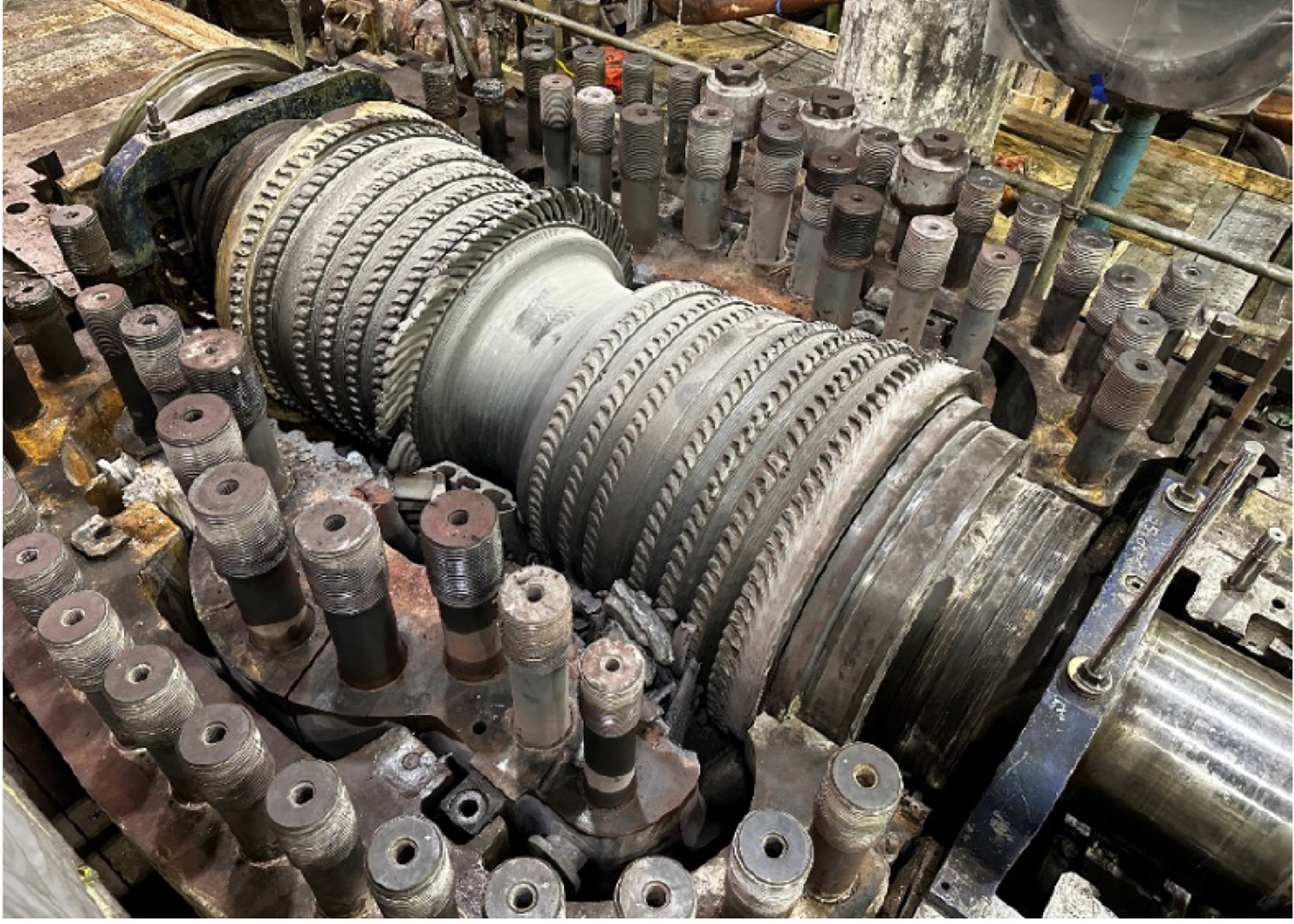
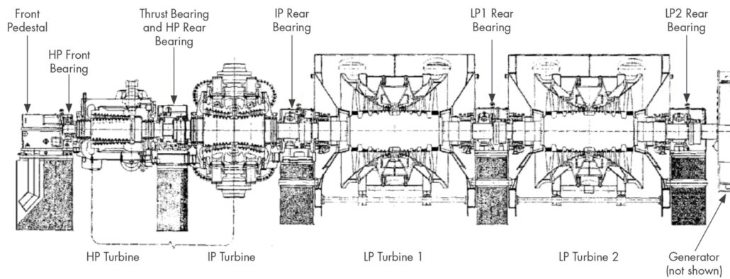
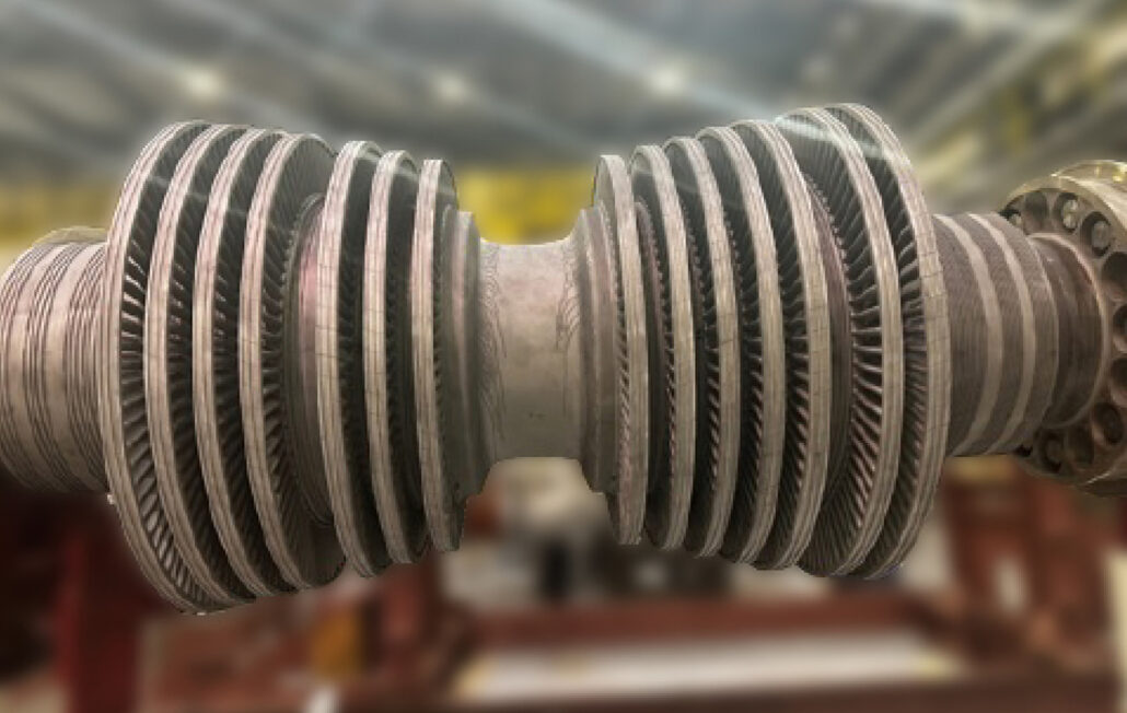
Initial investigation indicated severe damage to the HP, IP, and LP turbines (refer to rotor cross section in Figure 1). External observations of the STG indicated damage to piping and bearings along the drivetrain. The HP bearings and IP rear bearing were found heavily damaged with the bearing caps and coupling guards knocked off. The LP1 rear bearing was also identified to have coupling guard and bearing cap damage. The LP2 rear bearing and exciter showed damage to a lesser degree. Insulation damage was observed throughout the HP, IP, and LP crossover piping, along with damage to piping hangers and instrumentation.
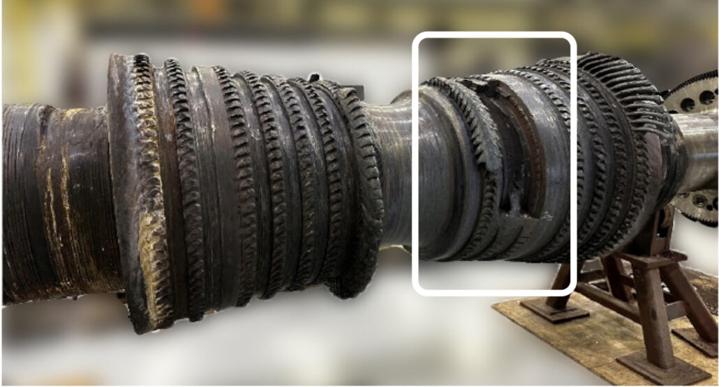
As the HP and IP rotors were disassembled, it became apparent that liberation of the IP rotor shaft and blade material was the initiating event. Removal of the IP inner cases revealed extensive damage to all stages of the IP rotating blades (Figure 2). The generator end first stage blades were heavily damaged, while the remaining stages were torn off at the airfoil base. A section of the rotor between the 2nd and 3rd stage blades had liberated (Figure 3), including the 2nd and 3rd stage blade roots in that region.
The HP turbine flow path was intact. Damage was observed in regions with tight radial clearances between rotating and stationary hardware, such as bearing packing regions and blade tip sealings. The damage observed in the HP turbine was consistent with excessive radial vibrations and / or a rotor whipping event. These observations confirmed that the HP damage was a result of the IP failure, and not vice versa.
The observed IP liberation resulted in significant imbalance and associated vibration of the IP shaft. With steam flow continuing, the liberated material likely migrated to downstream rotor and stationary blades resulting in additional liberation of blades and increased imbalance. The IP imbalance combined with continued steam flow to the entire shaft line, resulted in failure of bearings and their ability to contain the imbalance forces. As a result, considerable damage was imparted to turbine casings, piping systems, and other connected equipment.
SIA’s support for this event included:
- An onsite investigation of the turbine components
- Metallurgical evaluation of the damaged IP rotor
- Operational and maintenance review
- Thermal and Structural Analysis of the IP rotor
- Fatigue and creep lifing calculations
- A detailed causal analysis of the event
Rotor Metallurgical Evaluation
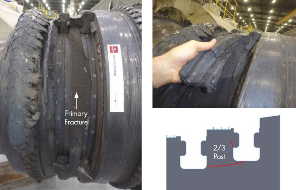
During SIA’s onsite inspection, we observed that the IP rotor material between blade rows 2 and 3 detached from the base rotor in an arch of approximately 120 degrees circumferentially. The primary fracture propagated from the outlet side of blade 2 bottom groove and progressed axially to the inlet side of blade 3 bottom groove (Figure 4). Secondary fractures radiated from the inlet blade 3 hook fitting and progressed axially toward the outlet blade 2 hook-fitting, radially through the wheel post hook, and at the ends of the liberated material.
Visual examination of the primary fracture surface shows an aged crack that progressed over time. Closer visual examination confirmed that the oldest surface was at the blade 2 outlet side. The surface had a “rock candy” appearance, which is a telltale indication of a creep driven failure.
SIA’s evaluation was based on visual and photographic examination of the rotor body and laboratory metallographic evaluation of the liberated rotor remnants whose mating surfaces were traceable. Due to post failure tumbling of the liberated material, the primary fracture was mechanically deformed at the inlet side, obscuring much of the fracture initiation region. However, evidence of creep cracking and bulk creep voids necklacing the grain boundaries was readily apparent (Figure 5). An oxide layer was observed further to the interior where post failure damage was absent. Grain boundaries at the initiation region exhibited significant deformation, consistent with post release tumbling damage.
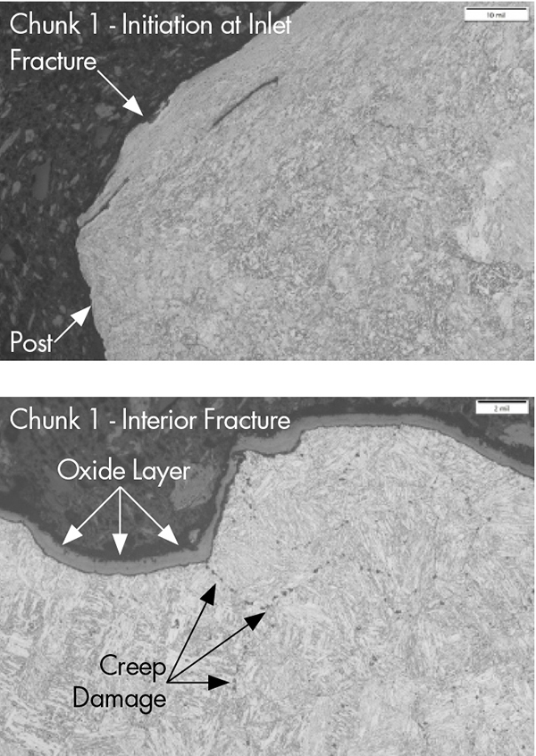
An undisturbed crack in the 2-3 post was mechanically opened and subsequently cross sectioned for metallographic analysis. Because the crack was closed, most of the initiation side (outlet side) was protected from post-failure impacts. Consequently, the initiation side provided good details on the state of the material in the affected region. As with the primary fracture, there was evidence of creep cracking, with fissuring and bulk creep voids necklacing the grain boundaries. A thick oxide layer was prominent at the initiation side and attenuated into the interior.
To quantify the fracture surface age, the protected secondary fracture surface was metallurgically examined, and oxide thickness measured. The average of the thickest areas was determined to be 6.8mils. SI utilized research data for 12 Cr steel that characterizes typical oxide growth over time to compute the approximate age. Oxide correlations were plotted for a range of measurements over a temperature range centered around SIA’s predicted 930°F at the secondary fracture location. From this data, SI estimated the crack age as between 50,000 and 100,000 hours of service.
All units at this site have experienced increased cycling in recent years, consistent with much of the US fleet. The IP rotor, in service since initial commissioning, had accumulated approximately 550 starts, with the majority of those events imposed in the last 10 years. With increased cycling, fatigue related damage and/or creep-fatigue (CF) interactions can significantly influence the operating life of an aging rotor.
CF interactions can range from fatigue dominated to creep dominated. In fatigue dominated CF, cracking will be intergranular (as was observed), with little creep cavitation and grain boundary voids remote from the crack region. In the creep dominated CF, notable grain boundary void accumulations are typically observed remote from the crack(s). This latter case is more consistent with the observations from the IP rotor. Although creep appears to be the dominant mechanism for crack growth, mechanical fatigue likely contributed to crack growth rates, particularly in low-cycle regions due to unit cycling.
Operational and Maintenance Review
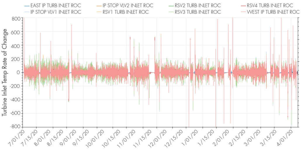
A review of the prior 3 years of operating data was performed, unit ramp rates and operating temperatures. The Rate of Change (ROC) in degrees per hour was plotted for all three units over a three-year period (Figure 6). The data identified rapid temperature changes during shutdowns and startups, with an incremental ROC of 133°F within a 10-minute period occurring regularly. Turbine manufacturers (OEMs) typically limit ROC to less than 50°F within a 10-minute period. Although cycling has imposed high ROCs, no metallurgical evidence was identified to indicate that cycling influenced or was the root cause of the IP rotor failure. However, it is reasonable to postulate that the CF interaction accelerated the primary fracture propagation rate. The effects of rapid startups may have a greater impact on components with less capable materials, such as the HP and IP turbine casings, the steam piping, and potentially the boilers themselves.
During the previous major outage where the IP rotor was removed, a crack was found on the generator end first stage inlet side blade slot bottom. Blade lift and looseness has been identified on the generator end first stage, prompting blade removal and subsequent identification of the blade slot cracking. The liquid penetrant test identified 3 total cracks, two near the bottom of the blade slot and one near the edge of the blade contact surface. A volumetric inspection of the solid inner portions of the rotor was performed; however, non-destructive examination (NDE) was NOT performed for the adjacent blade slots to inspect for similar cracking as that identified within stage 1.
Lifing Analysis of the IP Rotor
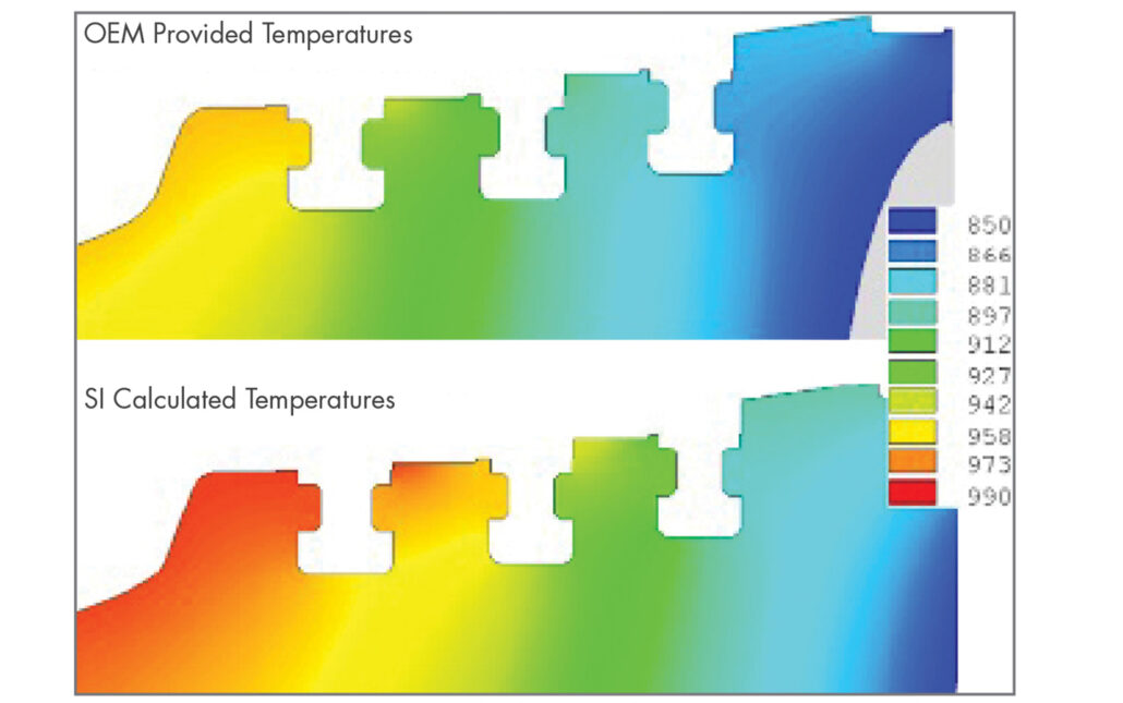
A finite element analysis (FEA) model of the IP rotor was developed from available/collected rotor dimensions. To investigate the correlation between operating temperatures and metallurgical findings, steady state, full load operating temperatures were calculated using blade geometry and the supplied heat balance diagram. The first stage blades were an impulse style design with the remaining stages configured as reaction style blades. Based on the blade style and flow path cross sectional areas and radial position, stage pressure ratios were calculated. Utilizing the heat balance and pressure ratios, steam energy balance calculations were iteratively solved to generate stage-by-stage temperatures and pressures.
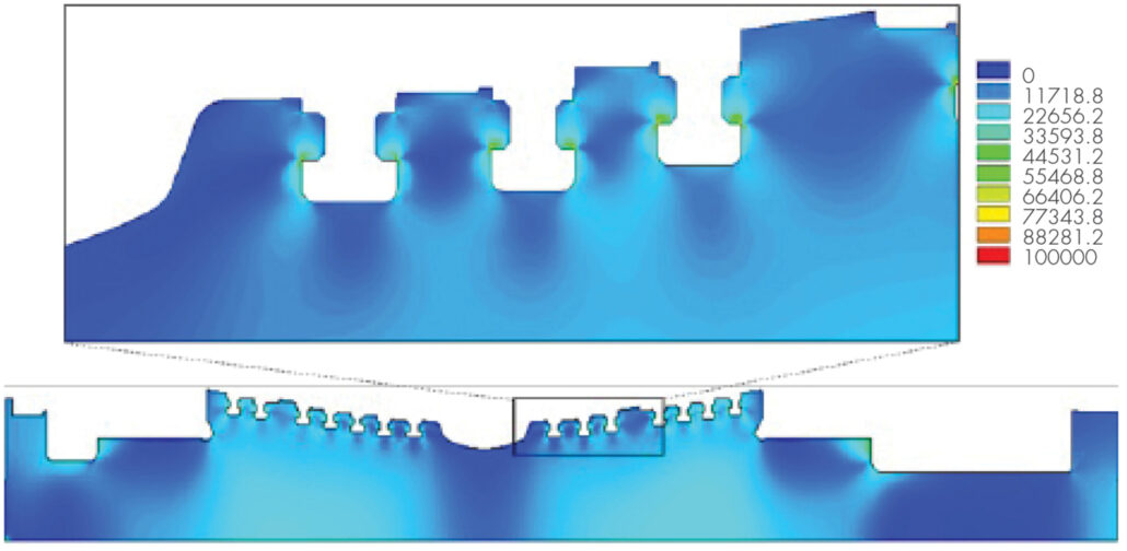
The OEM supplied stage temperatures would predict the 3rd stage rotor region to operate below 900°F, and underpredicted steam temperatures at downstream extractions. SIA’s calculated temperature profile better aligns with measured extraction and exhaust temperatures. Similarly, the 2-3 post predicted temperatures increased by approximately 30°F as compared to the OEM provided predictions (Figure 7). Steady state operating stresses were calculated to assist with lifing calculations (Figure 8). The results indicate the highest predicted elastic only stress is at the forward stage 3 hook where cracking was observed in the metallurgical analysis.
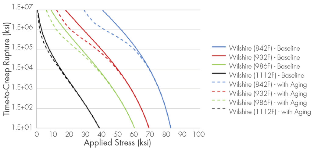
To support the estimation of creep rupture timeframes for key locations in the IP rotor, Wilshire curves were fitted to industry available 12 Cr rotor steel data. At high exposure hours (>100K hours), changes in the material microstructure can alter the mathematical trend of time-to-creep rupture versus applied stress. Thermal aging is a phenomenon corresponding to long-term, irreversible changes in the structure, composition, and morphology of a material when exposed to operational temperatures. In 12 Cr steels, thermal aging results in a reduction in the yield and ultimate tensile strengths, as a function of exposure time and temperature, and may cause a reduction in time-to-creep rupture at high exposure hours. The Wilshire Model was modified to account for aging effects and minimize extrapolation uncertainty beyond 100K operating hours (Figure 9).
Creep life predictions (time to creep rupture) were performed along two key paths within the IP rotor: 1) the first stage inlet side blade slot bottom, and 2) the 2-3 post path consistent with the event material liberation. Due to the multiaxial nature of the stresses in the IP rotor, as compared to the applied stresses during creep rupture testing, a modified Hayhurst-Huddleston approach was taken to collapse the principal stresses into a stress value to be used in the creep rupture model (Figure 10).
The resulting creep rupture inclusive average and minimum (approximating 3σ) life predictions were compared for the first stage inlet side blade slot bottom and 2-3 post event path. While the 2-3 post’s stress magnitude was greater, the first stage inlet side blade slot is predicted to operate approximately 50°F hotter resulting in a significantly shorter time to creep rupture. The resulting predictions for the first stage inlet side blade slot suggest an average life of 210,000 hours, with a minimum creep rupture prediction as early as 55,000 hours. The minimum creep rupture prediction for the 2-3 post was calculated as early as 250,000 hours.
Detailed Causal Analysis
A detailed causal analysis was completed by SIA’s team in support of the RCA. This investigation included:
- A detailed review of the metallurgical findings performed on the IP rotor material:
- Tertiary creep voids and creep cracking were identified in multiple 2-3 post features.
- There were no observed metallurgical features indicative of cycling influenced crack initiation.
- Surface oxidation indicates that both the primary fracture and radial hook cracks were present during the prior rotor out major outage.
- Analytical and empirical correlations of first stage inlet side blade slot cracking:
- Re-evaluation of metallurgical samples performed during the first stage repair in the prior major outage (243,000 hours) indicate the rotor had experienced advanced creep damage with chains of grain boundary creep voids present.
- Evaluation of sister IP rotors onsite indicated that similar first stage cracking had been historically experienced between 140,000 and 199,000 hours of operation.
- This rotor configuration has experienced significant creep degradation in less than 200,000 hours of operation. The stage 2-3 post, located about 6 inches axially downstream, operates under slightly reduced temperatures and comparable stress levels.
- The metallurgical evaluation did not identify any evidence to suggest that unit cycling influenced the IP rotor event. It is reasonable to postulate that the CF interaction accelerated the primary fracture propagation rate; however, cycling was not a root cause of the event.
- Prior outage inspection and fitness for service assessment:
- During the major outage and repair, IP first-stage cracking was identified upon removal of the blades. Volumetric NDE inspections were performed, however, this inspection was not focused in such a way that stage two and three blade slot indications would have been captured. With the age of the rotor and the crack findings in the first stage slots, the inspection of the adjacent slots should have been performed.
- Evidence of creep related damage was available to the service provider, however, miss-judgement of the damage mechanism led to an assumption that the rotor was serviceable without additional testing or inspections.
- No lifetime type evaluation was performed, and no rotor life prediction was available.
- It was recommended to re-inspect the first stage repair after 50,000 hours, but no similar guidance was provided for the remaining stages.
Through this causal analysis, the steam turbine event was determined to have occurred because of the liberation of a portion of the IP rotor stage 2–3-wheel post. The partial IP rotor wheel post liberation resulted from advanced creep degradation of the wheel post material. This creep occurred under prior and continued operation at normal operating temperatures and stresses beyond the capability of the rotor. The IP rotor remained in operation beyond its capability for two primary reasons.
- The owner of the equipment did not have a documented rotor life (i.e., completion of either an original or post service life assessment).
- The service provider communicated that the rotor could operate for 50,000 additional hours without the completion of a life assessment (the event occurred after approximately 26,000 hours of operation).
SIA’s Value as an Independent Partner
In support of the described event, SIA provided a detailed, independent root cause analysis, and recommendations for corrective and preventative actions. In addition to the event assessment, SIA developed customized inspection plans for the remaining units at the site and fleet risk management and inspection plans.
Customized Inspection for the Remaining Units
During the investigation, as the metallurgical degradation of the IP rotor was understood, SIA performed a risk assessment of the two sister units (3 total IP rotors, including a spare – Figure 11). Inspection of the first stage blade slot cracking was inconsistent (having never occurred for one of the two operating rotors, and more than 100,000 hours previously for a rotor with previous repairs). Similarly, inspection of the 2-3 post slot region had never been specifically performed.
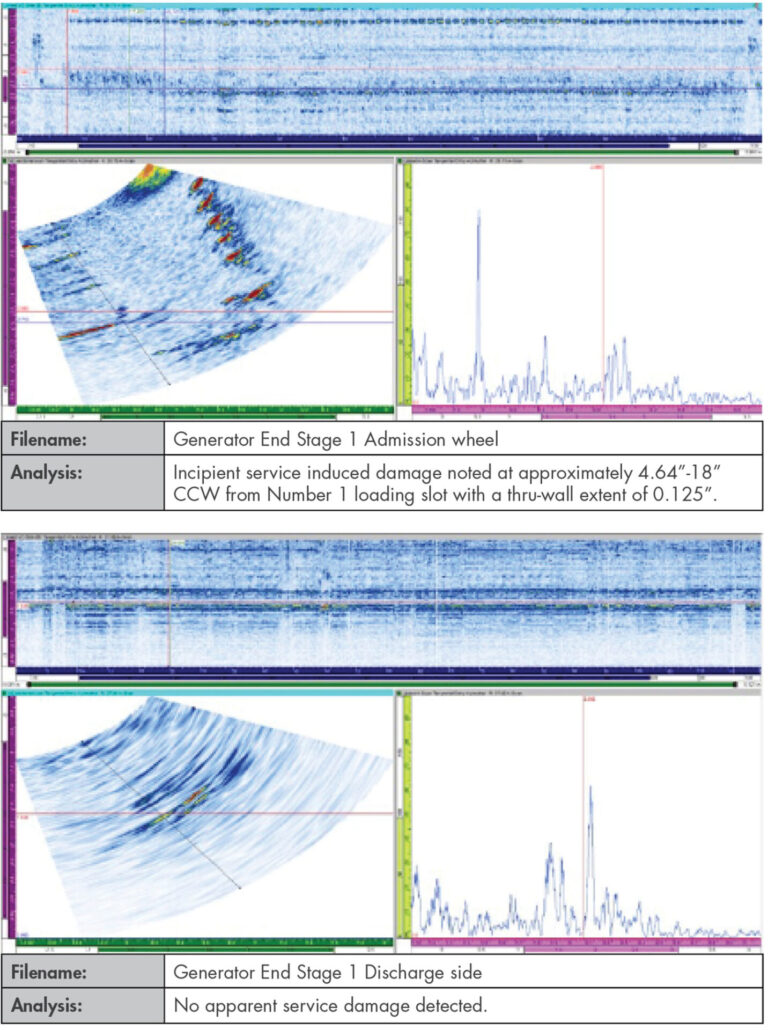
Where inspections had previously occurred based on blade lift measurements during planned outages, SIA utilized basic rotor cross section geometry to develop a NDE method for inspecting both the forward and aft blade slot geometries for the first 3 stages per flow. The site took advantage of market outages to disassemble the two sister IP turbines and removed the rotors for inspection. The first IP rotor, which had previously had a stage one post weld repair performed, remained clear of any service induced damage in stage 1 through 3 slot regions. The second rotor, which had no prior repairs, was identified to have first stage slot cracking later confirmed by penetrant testing with the blades removed (Figure 12).
SIA helped the site manage the risk of continued operation of its existing aging assets through minimally invasive NDE inspections tailored to suit its geometry and operating profile.
Fleet Risk Management and Inspection Planning
To support the utility’s remaining aging fleet, SIA performed a fleet risk assessment of its remaining large steam drivetrains.
This assessment includes an evaluation of each rotor including:
- Total hours and starts
- Quality of Inspections and Operation Since Last Inspection
- Operating conditions (steam temperature and quality)
- Operating Stresses
- Rotor Construction:
- Forging vintage and material specification requirements
- Crack tolerance and impacts of aging effects
- ν Operation based degradation modes:
- Time dependent modes (Creep Rupture, Stress Corrosion Cracking, etc.)
- Cycles dependent modes (Fatigue, etc.)
The fleet risk assessment provided risk rankings for each degradation mode as well as rotor specific and unit specific risk. The assessment identified fleet outliers based on embrittlement susceptible forgings as well as previously deferred maintenance inspections.
As rotors age beyond their design operating period, operating intervals should be re-evaluated based on rotor and material specific degradation modes and desired operating profiles. Accumulated damage from operating hours and startups combined with material aging effects will degrade material capability and reduce tolerance to service induced damage.
Rotor inspection prioritization by risk and optimization by degradation specific modes and locations can keep assets operating safely and support reasonable outage planning and replacement timelines. An informed rotor life management approach probabilistically accounts for short- and long-term rotor degradation in future re-inspection intervals, inspection scopes and risk planning.
DOWNLOAD FULL ISSUE