News & Views, Volume 53 | Materials Lab Featured Damage Mechanism
CIRCUMFERENTIAL THERMAL FATIGUE IN CONVENTIONAL WATERWALL TUBES
By: Wendy Weiss
Circumferential Thermal Fatigue damage in Conventional Waterwall Tubes most commonly appears as circumferentially oriented cracking in the waterwalls of coal-fired supercritical units. Initially, the formation of ripple magnetite was a significant factor in the formation of this damage. Later, the introduction of oxygenated treatment controlled the formation of ripple magnetite, thus greatly reducing this damage mechanism. In the early 2000s, however, this type of thermal fatigue began occurring more frequently as low NOx burners and separated overfire air systems were introduced.
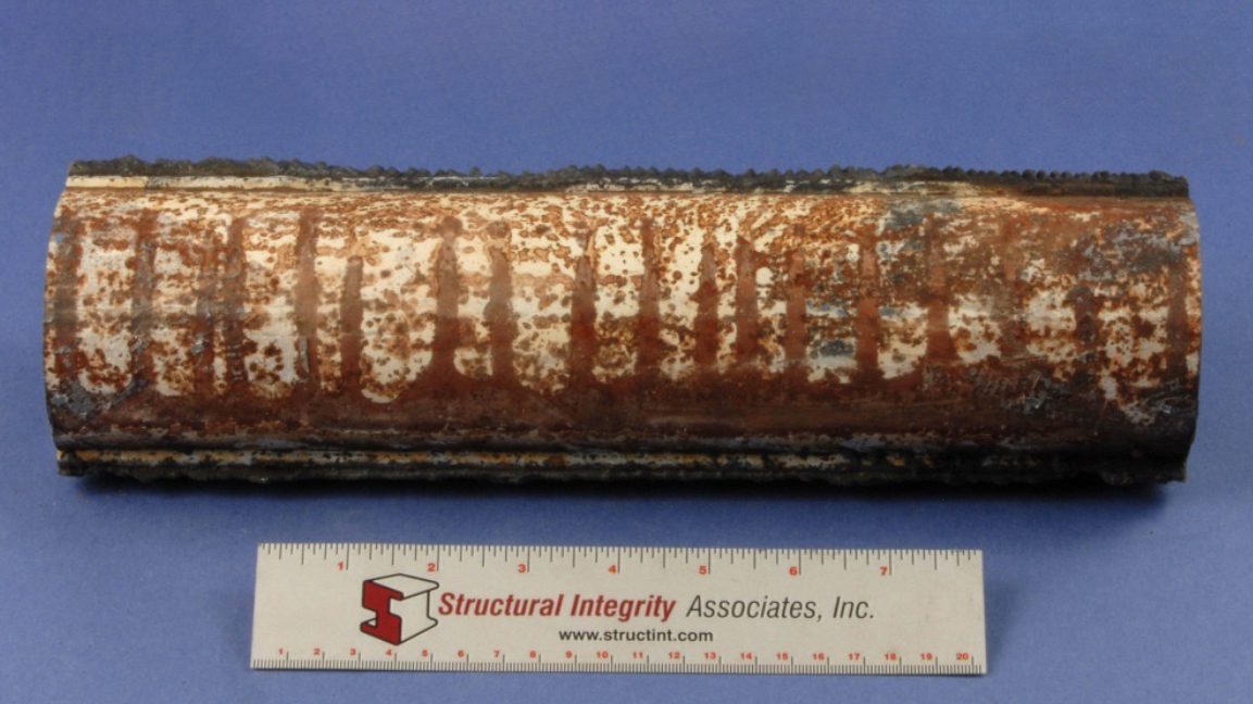
Figure 1. Tube with a series of circumferential cracks
Mechanism
Three basic factors contribute to this type of thermal fatigue damage.
- The first factor is the starting tube temperature (i.e., the temperature under normal operating conditions). The higher the starting temperature, the greater the accumulation of damage in the affected tubing. For example, tubes subjected to higher heat flux or tubes with thick weld overlays will have higher average metal temperatures and accumulate damage more quickly.
- The second factor is the extent of gradually increasing tube temperature caused by reasons such as internal deposit buildup, flame impingement, or unstable flow.
- The third factor is the contribution of thermal transients due to slag shedding or using sootblowers or water cannons.
Essentially, the thermal fatigue cracking results from the combination of increasing tube metal temperature and thermal transients and is aggravated by high starting tube temperatures.
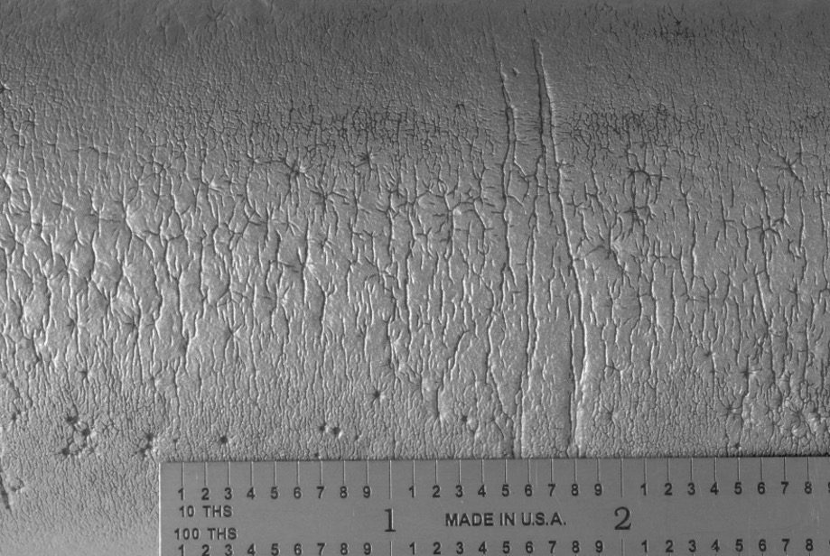
Figure 2. The external surface of the tube after the external deposits were removed
TYPICAL LOCATIONS
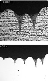
Figure 3. Cross-sectional views of the cracking in the etched (Top) and unetched (BOTTOM) conditions
- Tubes with slag buildup and shedding
- Areas affected by wall blow quenching
- High heat flux locations
- Areas affected by flame impingement
- Cracking can be localized or widespread
- Tends to be contained within a relatively narrow range of elevations
FEATURES
- Circumferentially oriented, multiple, parallel cracks along the hot side of the tubes.
- Notch shaped, oxide filled cracks in cross-section.
- Adjacent tubes can exhibit variability in crack density.
ROOT CAUSES
- High Initial Waterwall Tube Temperatures
- Thick weld overlays
- Higher heat flux
- Flame impingement
- Increasing Waterwall Tube Temperatures
- Internal deposits including ripple magnetite, thick oxide layers, or feedwater corrosion products
- Reduced internal flow rate
- Formation of external oxides and deposits
- Severe Thermal Transients
- Natural or forced slag removal, including slag shedding and sootblowing
- Use of water cannons or improper sootblowing
- Flame instabilities
- Unit operation, including forced fan cooling, rapid startups, frequent load cycling


