
News and Views, Volume 55 | Materials Lab Featured Damage Mechanism
CREEP FATIGUE IN STEAM COOLED BOILER AND HRSG TUBES
By: Wendy Weiss
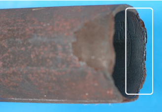
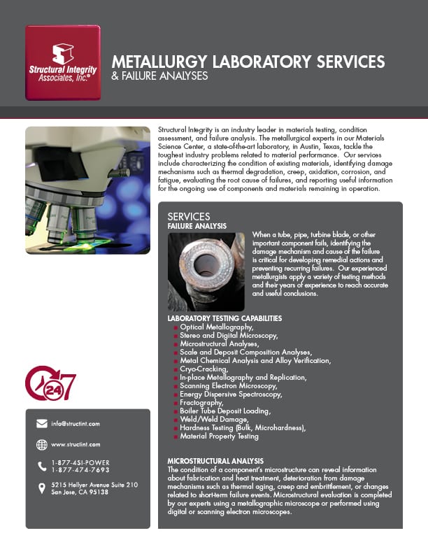
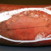
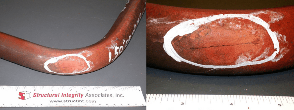
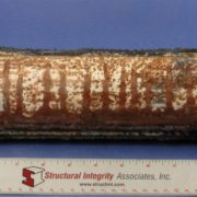
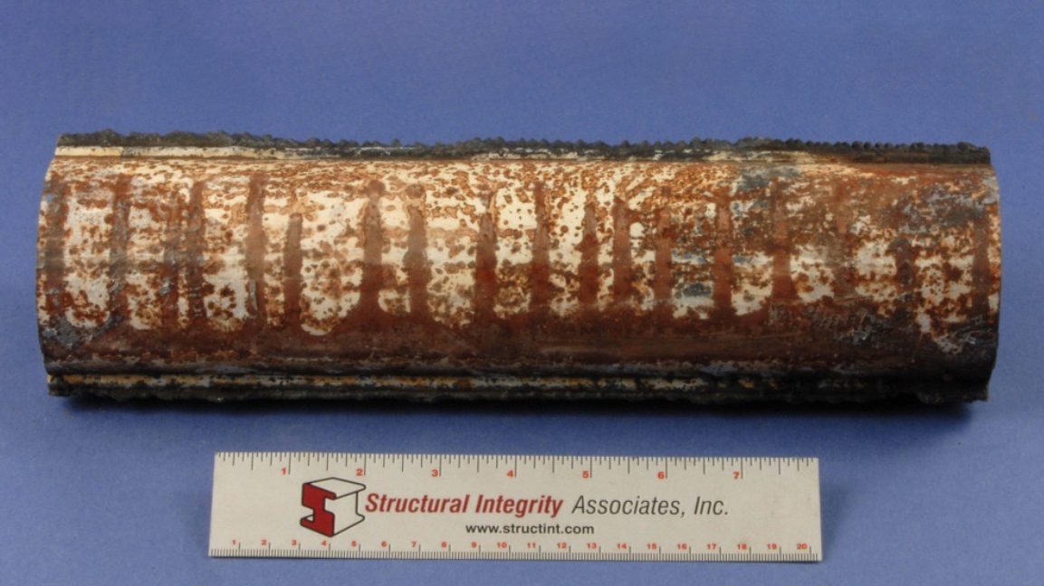
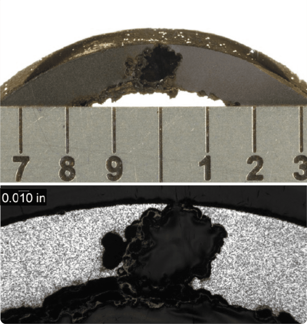
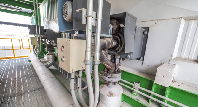
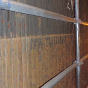
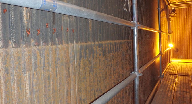
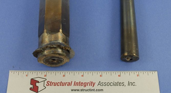
Figure 1. Tube to header weld crack.
Creep-fatigue is caused by the accumulation of damage through synergistic interaction of cyclic stress and elevated operating temperature. The creep and fatigue components of the damage usually occur at different periods in the thermal cycle to result in a failure with characteristics of both mechanisms. Structural Integrity has an experienced group of materials specialists and a full-service metallurgical testing laboratory that can help with any situation involving material property characterization.
Creep-fatigue is generally assumed to be the active mechanism when the rate of fatigue damage is influenced by the strain rate and hold times while the tube is operating at temperatures within its creep regime.
Mechanism
Creep-fatigue is essentially the accumulation of damage through synergistic interaction of cyclic stress and an elevated operating temperature. The creep and fatigue components of the damage usually occur at different periods in the thermal cycle. Cyclic loading may occur at temperatures within the material’s creep regime (≥800°F for Cr-Mo tubing). Once steady state conditions are reached, the component may continue to be exposed to high temperatures and localized stresses, which can result in the accumulation of additional plastic strains due to creep. Furthermore, if residual stresses due to thermal transients were present, creep relaxation would add to the magnitude of the inelastic strain. The key takeaway regarding creep-fatigue damage is that the fatigue life can be significantly less than would be predicted from pure fatigue test data.
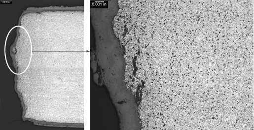
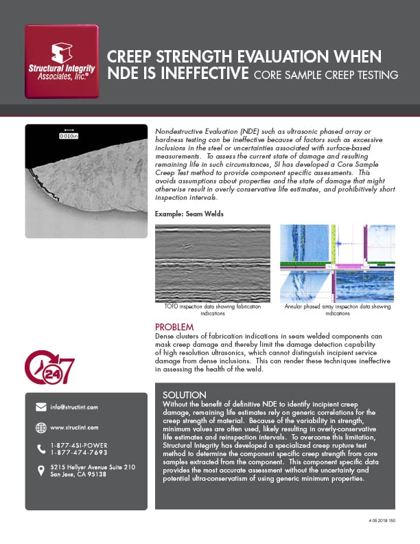
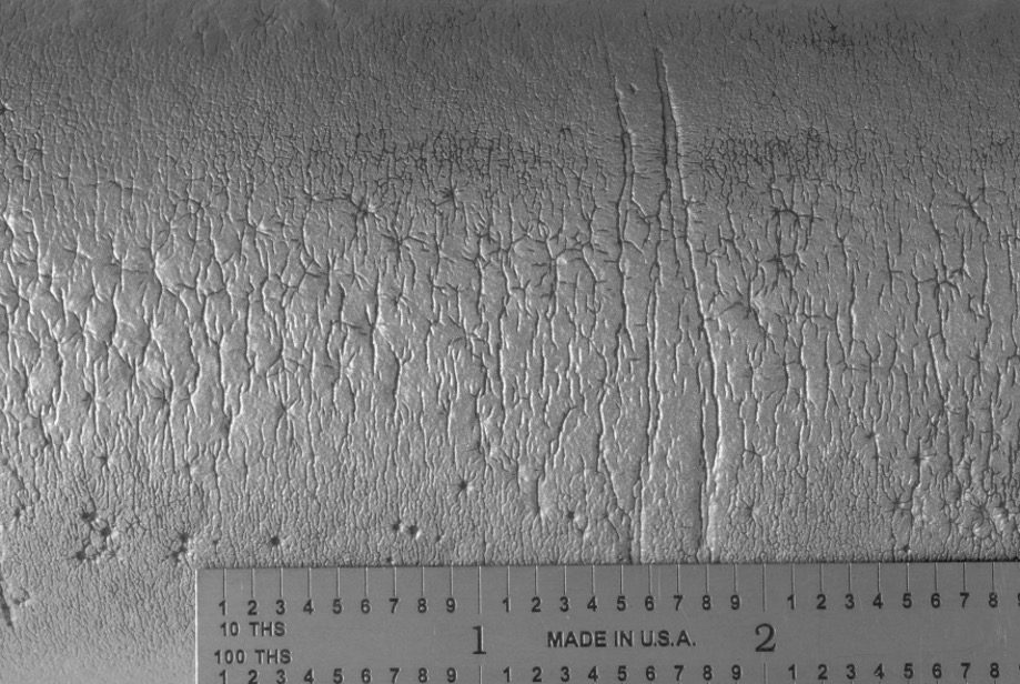
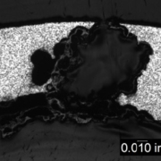
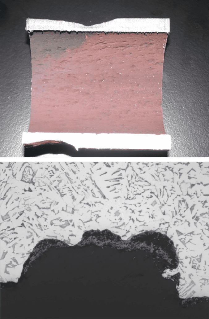
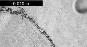
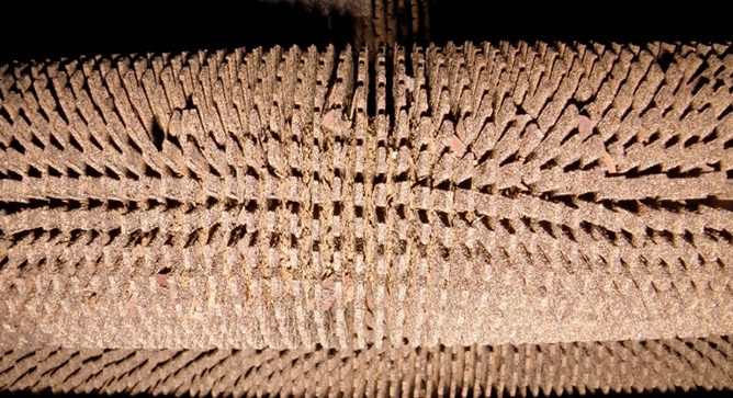
Figure 2. Crack surface of the tube to header weld crack, with a thick oxide layer and creep damage along its length.
Typical Locations
- Superheater and reheater tubes where tube metal temperatures are in the creep regime
- Welded connections
- Bends
- Tube-to-header attachments
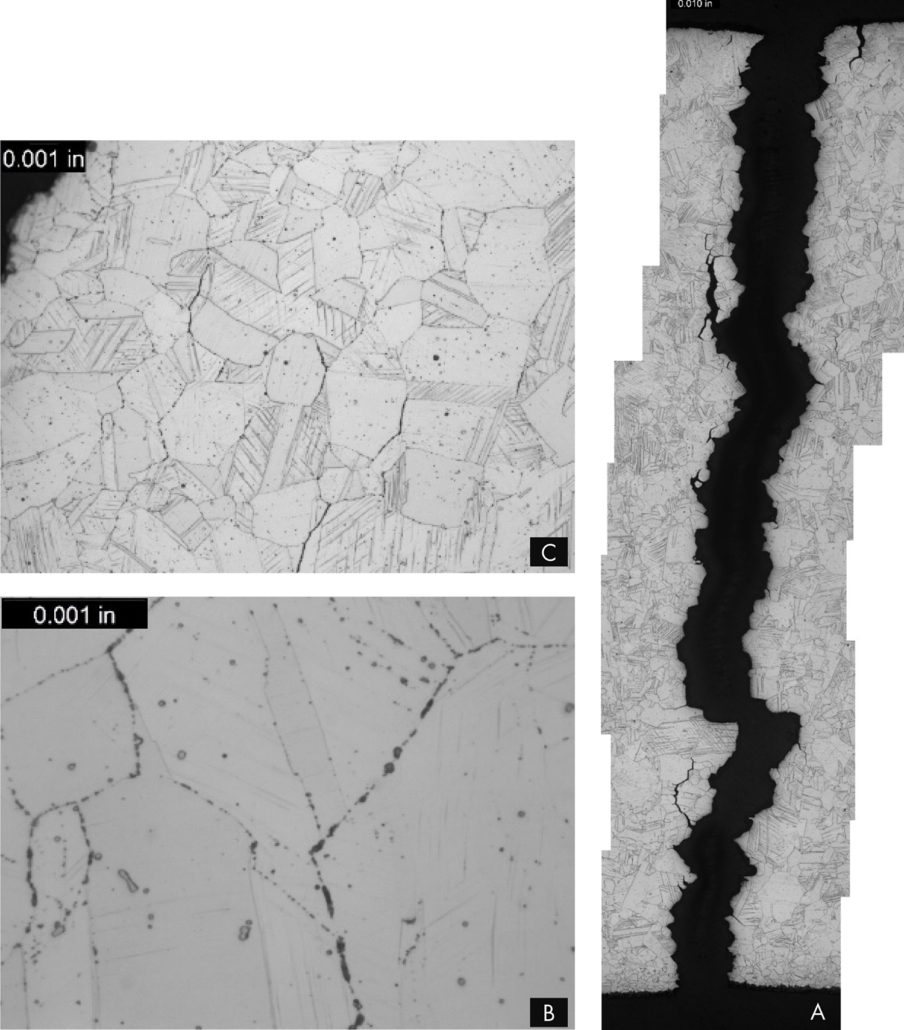
Features
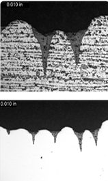
- Generally initiates on the OD surface
- Typically, single cracks
- Cracks are generally relatively straight, relatively wide, and oxide-filled or oxide-lined
- Creep voids and microfissures can surround the primary crack, but creep damage does not have to be present
Root Causes
Creep-fatigue is caused by the interaction of stresses, both cyclic and static, and elevated temperature exposure. Root causes can include excessive stresses/strains, excessive tube temperatures, and unit operation.
Excessive stresses/strains can result from the following, many of which are related to HRSG operation: constrained thermal expansion, pressure changes, fluid temperature changes, non-uniform temperatures, load transfer between hot and cold conditions, changes in external loads, transient temperature differences, steam or water hammer, forced vibration, flue gas flow problems, thermal transients due to condensate flashing into tube circuits, improper attemperation, and incorrect or inadequate drains.
Excessive tube temperatures can result from excessive temperature ramp rates, poor distribution of tube temperatures, poorly designed thickness transitions at header connections and supports, and poor material selection for tubing.
The number of service hours, number of stop/starts, and the characteristics of the stop/starts are unit operation influences that can affect creep-fatigue damage.
Visit Our Metallurgical Laboratory Services Page
SEE THESE OTHER RELATED MATERIALS FROM THE SIA METALLURGICAL LABORATORY
Featured Articles


Metallurgical Laboratory Product & Services Information
Failure Analysis
SI Overview
Metallurgy Laboratory Services & Failure Analyses
Creep Strength Evaluation When NDE Is Ineffective Core Sample Creep Testing
In-house Materials Laboratory Capabilities
Materials Laboratory Case Study 1 | Manufacturing – Process Upsets
Materials Laboratory Case Study 2 | Manufacturing – Supply Chain Upsets
Materials Laboratory Case Study 3 | Infrastructure Upgrades – Material Verification
Materials Laboratory Case Study 4 | Infrastructure Upgrades – Materials Analysis
Materials Laboratory Case Study 5 | Process Upsets – Condition Analysis
 By: Wendy Weiss
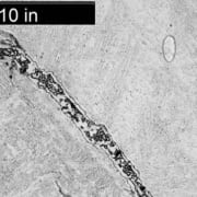
 Structural Integrity (SI)
 Industry experience shows that waterwall tubing in conventional boilers can be susceptible to fireside corrosion, depending on fuel type, firing practice, etc. In boilers where fireside corrosion has been identified as a maintenance issue, wastage rates of 5 to 25 mils/year are not uncommon. Since the mid 1990s, the installation of low NOx burner systems designed to lower NOx emissions has significantly increased the wastage rates in some boilers. Operators of subcritical boilers have reported wastage rates as high as 30 mils/year, while those operating supercritical boilers have reported rates exceeding 100 mils/year in the worst cases. These higher damage rates have resulted in an increase in tube failures, and operators have struggled to accurately define the extent of the damage and install the appropriate mitigating technologies.
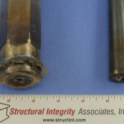
 Structural Integrity (SI) was recently asked to examine a fractured thermowell and determine the damage mechanism.
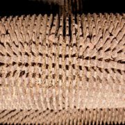
 Acid dewpoint corrosion can occur in conventional and HRSG units in locations where temperatures fall below the sulfuric acid dewpoint temperature. This can occur when either the tube metal temperatures are below the acid dewpoint so that condensate forms on the metal surface, or when flue gas temperatures are below the acid dewpoint, so that the condensate will form on fly ash particles.