News and Views, Volume 54 | Materials Lab Featured Damage Mechanism

STRAIN-INDUCED PRECIPITATION HARDENING (SIPH) IN AUSTENITIC STAINLESS BOILER TUBES

By:  Wendy Weiss

Structural Integrity’s Metallurgical Laboratory offers comprehensive metallurgical laboratory services to support client material issues.

Strain-Induced Precipitation Hardening, also known as SIPH, is a commonly misinterpreted boiler tube failure mechanism that occurs when austenitic stainless steel tubing is cold or warm worked during fabrication and then is installed with either improper or no solution annealing heat treatment. While the basic mechanism and the root cause are understood, the complex interaction between heat chemistry, quantity of cold or warm work, and subsequent thermal history makes it very difficult to predict under precisely what circumstances damage due to SIPH will result in failure of a boiler tube.

Longitudinally oriented crack at the extrados of a bend in a stainless steel superheater tube.

Mechanism
SIPH occurs when a heat of austenitic stainless steel containing certain precipitate-forming elements (e.g., niobium, titanium, vanadium, etc.) either intentionally or as residuals is cold or warm worked during subsequent material processing. The cold or warm working creates excess defects in the sub-structure of the material, which serve as preferred sites for precipitation of temper-resistant carbides or carbo-nitrides. Precipitation occurs when the material is heated to a sufficiently high temperature that is well below the solution annealing temperature. This can occur rapidly during a poorly executed heat treatment if the material does not reach the proper solution annealing temperature, or it can occur more slowly at typical operating temperatures for superheater or reheater tubing in utility-type boilers.

Once formed, precipitates anchor to the defects, resulting in a substantial increase in the elevated temperature or creep strength of the interior of the grains. At the same time, there is a narrow zone of material immediately adjoining the grain boundaries that remains largely precipitate-free due to the diffusional characteristics of the grain boundary itself. Ultimately, the interior portion of the individual grains becomes very strong at elevated temperatures while the material immediately adjoining the grain boundaries becomes comparatively creep weak. In addition, any surface-active elements that may be present in the material, such as arsenic, tin, antimony, etc., will tend to concentrate at the grain boundaries, further reducing their strength.

Regardless of when the precipitation occurs, once the interior of the grains has been strengthened, the grain boundary regions are weakened. Any strain imposed on the material in response to an applied or residual stress is forced to concentrate in the grain boundary region, which substantially magnifies its effect. For example, suppose the bulk strain experienced by a cold-worked stainless superheater tube segment is very small – a fraction of a percent – and the material has undergone the SIPH reaction. The strengthened grain interiors will undergo no strain. Conversely, within the much smaller volume of the comparatively weak grain boundaries, the accumulated strain will be orders of magnitude higher than the bulk level.

Typical Locations

  • Bends
  • Offsets
  • Swages
  • Welded attachments

Features

  • Can initiate at midwall
  • Early-stage damage consists largely of grain boundary cavities and microfissures
  • Intergranular cracking

Root Causes
The single root cause of SIPH is the failure to properly solution anneal susceptible heats of austenitic stainless steel tubing that has been either cold or warm worked during fabrication.

An overall, cross-sectional view of the intergranular crack (image A) with higher magnification views of some of the secondary grain boundary microfissures and voids (image C). Slip bands (parallel lines in image B) indicate local deformation.

For any situation involving material property characterization, Structural Integrity has an experienced group of materials specialists and a full-service metallurgical testing laboratory that can help.

Visit Our Metallurgical Laboratory Services Page

SEE THESE OTHER RELATED MATERIALS FROM THE SIA METALLURGICAL LABORATORY

Metallurgical Laboratory Product & Services Information


News & Views, Volume 53 | Materials Lab Featured Damage Mechanism

CIRCUMFERENTIAL THERMAL FATIGUE IN CONVENTIONAL WATERWALL TUBES

By:  Wendy Weiss

Circumferential Thermal Fatigue damage in Conventional Waterwall Tubes most commonly appears as circumferentially oriented cracking in the waterwalls of coal-fired supercritical units. Initially, the formation of ripple magnetite was a significant factor in the formation of this damage. Later, the introduction of oxygenated treatment controlled the formation of ripple magnetite, thus greatly reducing this damage mechanism.  In the early 2000s, however, this type of thermal fatigue began occurring more frequently as low NOx burners and separated overfire air systems were introduced. 

Figure 1. Tube with a series of circumferential cracks

Mechanism

Three basic factors contribute to this type of thermal fatigue damage. 

  1. The first factor is the starting tube temperature (i.e., the temperature under normal operating conditions). The higher the starting temperature, the greater the accumulation of damage in the affected tubing. For example, tubes subjected to higher heat flux or tubes with thick weld overlays will have higher average metal temperatures and accumulate damage more quickly. 
  2. The second factor is the extent of gradually increasing tube temperature caused by reasons such as internal deposit buildup, flame impingement, or unstable flow. 
  3. The third factor is the contribution of thermal transients due to slag shedding or using sootblowers or water cannons. 

Essentially, the thermal fatigue cracking results from the combination of increasing tube metal temperature and thermal transients and is aggravated by high starting tube temperatures. 

Figure 2. The external surface of the tube after the external deposits were removed

TYPICAL LOCATIONS

Figure 3. Cross-sectional views of the cracking in the etched (Top) and unetched (BOTTOM) conditions

  • Tubes with slag buildup and shedding
  • Areas affected by wall blow quenching
  • High heat flux locations
  • Areas affected by flame impingement
  • Cracking can be localized or widespread
  • Tends to be contained within a relatively narrow range of elevations

FEATURES

  • Circumferentially oriented, multiple, parallel cracks along the hot side of the tubes.
  • Notch shaped, oxide filled cracks in cross-section.
  • Adjacent tubes can exhibit variability in crack density.

ROOT CAUSES

  • High Initial Waterwall Tube Temperatures
    • Thick weld overlays
    • Higher heat flux
    • Flame impingement
  • Increasing Waterwall Tube Temperatures
    • Internal deposits including ripple magnetite, thick oxide layers, or feedwater corrosion products
    • Reduced internal flow rate
    • Formation of external oxides and deposits
  • Severe Thermal Transients
    • Natural or forced slag removal, including slag shedding and sootblowing
    • Use of water cannons or improper sootblowing
    • Flame instabilities
    • Unit operation, including forced fan cooling, rapid startups, frequent load cycling

Get News & Views, Volume 53

Structural Integrity Associates | News and Views, Volume 51 | Optical Microscopy | Applications and Benefits

News & Views, Volume 51 | Optical Microscopy Applications and Benefits

By:  Clark McDonald

In the world of metallurgical failure analysis, areas of interest on broken parts can be colorful or drab, three-dimensional or flat, and most importantly, very big or very small.  A big part of failure analysis work is telling the story, explaining the failure mode, or in some cases, showing that critical piece of evidence that explains why a metal component has failed.  From wide-angled lenses to extremely high magnification scanning electron microscope imagery, documentation of failed components is a big part of the presentation.  

In this edition of Structural Integrity’s Lab Corner, we wanted to provide some interesting content related to that middle-of-the-road region of magnification; closer than macro-photography but farther away than the 100X to 5000X magnifications that cover most of the applications requiring scanning electron microscopy.  In other words, the comfortable world of optical microscopy, where colors, shapes, and even surface textures are part of the story.  To do this, we’ve chosen some images that show the usefulness of quality optical microscopic documentation.  Each of the provided examples include a brief description along with specific comments on the benefits of optical microscopy for that project, where applicable.

Figure 1. Two- and three-dimensional color images of an aluminum annode plate showing light-colored deposits that have caused uneven wastage. The 3D image shows the extent of material removal in locations where deposits are not present. Normal wastage in this application should be uniform.

Figure 2. Two- and three-dimensional color images showing fastener thread flank damage and a crack origin near the root of the upper thread. The 3D image shows that the crack origin is located on the thread flank rather than at the deepest part of the thread root.

Figure 3. Two- and three-dimensional images of a copper heat exchanger tube that has been damaged from under-deposit corrosion (UDC). The image at left shows the typical appearance of the ID deposits. The center image shows a region of damage surrounding a pinhole leak. The 3D image provides an idea of the depth of internal corrosion in the tube.

Figure 4. Two- and three-dimensional images of a region of damage on an internal surface of a feedwater pump. The image at left shows the appearance of brownish deposits found within the corroded region of the pump surface. The 3D image provides an indication of the depth and shape of the corrosion damaged region.

Figure 5. Two dimensional stitched image of a weld cross section showing cracking emanating from a shallow weld root. Porosity is also visible in multiple locations in the weld.

Figure 6. Images of a region of damage on the exterior of a heat exchanger tube where wastage has occurred near the tube sheet. The upper right image is a view of the leak location with an overlay of lines showing the position where the surface profile was documented as well as the depth profile (overlaid and in the lower image). The upper left image, which has an appearance similar to an x-ray, is a side view of the 3D image of the tube surface.

Get News & Views, Volume 51

Structural Integrity Associates | News and Views, Volume 51 | Pitting Corrosion in Conventional Fossil Boilers and Combined Cycle:HRSGs

News & Views, Volume 51 | Materials Lab Featured Damage Mechanism

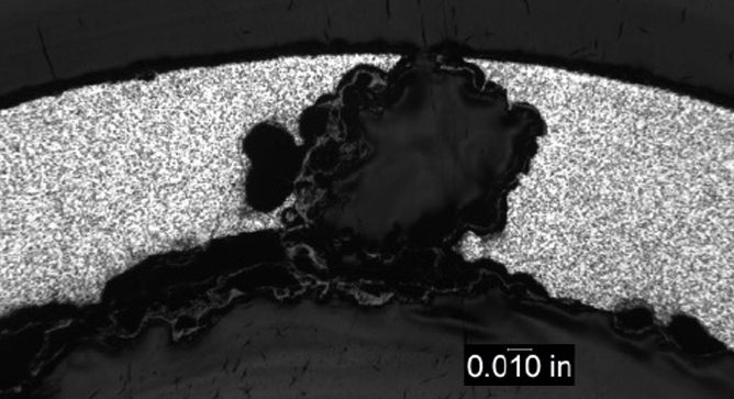
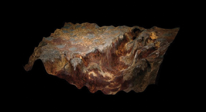
PITTING CORROSION IN CONVENTIONAL FOSSIL BOILERS AND COMBINED CYCLE/HRSGS

By:  Wendy Weiss

Pitting is a localized corrosion phenomenon in which a relatively small loss of metal can result in the catastrophic failure of a tube. Pitting can also be the precursor to other damage mechanisms, including corrosion fatigue and stress corrosion cracking. Pits often are small and may be filled with corrosion products or oxide, so that identification of the severity of pitting attack by visual examination can be difficult. 

Figure 1. Severe pitting in a tube from a package boiler

Mechanism 

Pitting is a localized corrosion attack involving dissolution of the tube metal surface in a small and well-defined area. Pitting corrosion can occur in any component in contact with water under stagnant oxygenated conditions. Pitting in economizer tubing is typically the result of poor shutdown practices that allow contact with highly-oxygenated, stagnant water. Pitting also may occur in waterwall tubing as a result of acidic attack stemming from an unsatisfactory chemical cleaning or acidic contamination. 

Pits that are associated with low pH conditions tend to be numerous and spaced fairly close together. The pits tend to be deep-walled compared to the length of the defect. A breakdown of the passive metal surface initiates the pitting process under stagnant oxygenated conditions. A large potential difference develops between the small area of the initiated active pit (anode) and the passive area around the pit (cathode). The pit will grow in the presence of a concentrated salt or acidic species. The metal ion salt (M+A-) combines with water and forms a metal hydroxide and a corresponding free acid (e.g., hydrochloric acid when chloride is present). Oxygen reduction at the cathode suppresses the corrosion around the edges of the pit, but inside the pit the rate of attack increases as the local environment within the pit becomes more acidic. In the event that the surfaces along the walls of the pit are not repassivated, the rate of pit growth will continue to increase since the reaction is no longer governed by the bulk fluid environment. Pitting is frequently encountered in stagnant conditions that allow the site initiation and concentration, allowing the attack to continue. 

The most common cause of pitting in steam touched tubing results from oxygen rich stagnant condensate formed during shutdown. Forced cooling and / or improper draining and venting of assemblies may result in the presence of excess moisture. The interface between the liquid and air is the area of highest susceptibility. Pitting can also be accelerated if conditions allow deposition of salts such as sodium sulfate that combine with moisture during shutdown. Volatile carryover is a function of drum pressure, while mechanical carryover can increase when operating with a high drum level or holes in the drum separators. Pitting due to the effects of sodium sulfate may occur in the reheater sections of conventional and HRSG units because the sulfate is less soluble and deposits on the internal surfaces. During shutdowns the moisture that forms then is more acidic. 

Figure 2. Pitting on the ID surface of a waterwall tube

Typical Locations

In conventional units, pitting occurs in areas where condensate can form and remain as liquid during shutdown if the assemblies are not properly vented, drained, or flushed out with air or inert gas. These areas include horizontal economizer tubes and at the bottom of pendant bends or at low points in sagging horizontal tubes in steam touched tubes. 

In HRSGs, damage occurs on surfaces of any component that is intentionally maintained wet during idle periods or is subject to either water retention due to incomplete draining or condensation during idle periods. 

Attack from improper chemical cleaning activities is typically intensified at weld heat affected zones or where deposits may have survived the cleaning. 

Features

Pits often are small in size and may be filled with corrosion products or oxide, so that identification of the severity of pitting attack by visual examination can be difficult. 

Damage to affected surfaces tends to be deep relative to pit width, such that the aspect ratio is a distinguishing feature. 

Root Causes

Figure 3. Pitting on the ID surface of an economizer tube

The primary factor that promotes pitting in boiler tubing is related to poor shutdown practices that allow the formation and persistence of stagnant, oxygenated water with no protective environment. Confirming the presence of stagnant water includes: 

  1. analysis of the corrosion products in and around the pit; 
  2. tube sampling in affected areas to determine the presence of localized corrosion; and 
  3. evaluation of shutdown procedures to verify that conditions promoting stagnant water exist. 

Carryover of sodium sulfate and deposition in the reheater may result in the formation of acidic solutions during unprotected shutdown and can result in pitting attack. Similarly flyash may be pulled into reheater tubing under vacuum and form an acidic environment.

Get News & Views, Volume 51

News & Views, Volume 49 | Materials Lab Featured Damage Mechanism - Soot Blower Erosion

News & Views, Volume 49 | Materials Lab Featured Damage Mechanism: Soot Blower Erosion

News & Views, Volume 49 | Materials Lab Featured Damage Mechanism - Soot Blower ErosionBy:  Wendy Weiss

Soot blower erosion (SBE) is caused by mechanical removal of tube material due to the impingement on the tube wall of particles entrained in the “wet” blower steam. As the erosion becomes more severe, the tube wall thickness is reduced and eventually internal pressure causes the tube rupture.

Mechanism

SBE is due to the loss of tube material caused by the impingement of ash particles entrained in the blowing steam on the tube OD surface.  In addition to the direct loss of material by the mechanical erosion, SBE also removes the protective fireside oxide. (Where the erosion only affects the protective oxide layer on the fireside surface, the damage is more properly characterized as erosion-corrosion.) Due to the parabolic nature of the oxidation process, the fireside oxidation rate of the freshly exposed metal is increased. The rate of damage caused by the steam is related to the velocity and physical properties of the ash, the velocity of the particles and the approach or impact angle. While the damage sustained by the tube is a function of its resistance to erosion, its composition, and its operating temperature, the properties of the impinging particles are more influential in determining the rate of wall loss.

READ MORE

News & Views, Volume 49 | Hydroelectric Penstock Inspection - Field NDE Services

News & Views, Volume 49 | Hydroelectric Penstock Inspection: Field NDE Services

News & Views, Volume 49 | Hydroelectric Penstock Inspection - Field NDE ServicesBy:  Jason Van Velsor and Jeff Milligan

Our talented experts, using the latest technology and methods, deliver unmatched value, actionable information, and engineering knowledge for the management of your most critical assets.

Many of the penstocks used in the hydroelectric power industry have been in service for over 50 years.  Often with older components, historical documents like, as-built drawings and proof of material composition no longer exist.  This information is critical for inspection, repair and replacement decisions.  SI has the expertise to assist hydro clients with everything from material verification, inspection, and fitness-for-service analysis to keep penstock assets in-service for many more years to come.

READ MORE

News & Views, Volume 48 | Metallurgical Lab Case Study – Grade 91 Elbows Cracked Before Installation

By:  Wendy Weiss and Terry Totemeier

News & View, Volume 48 | Metallurgical Lab Case Study - Grade 91 Elbows Cracked Before InstallationStructural Integrity (SI) personnel visited a power plant construction site to examine four Grade 91 elbows (ASTM A234-WP91 20-inch OD Sch. 60) that were found to contain axially oriented surface indications. The elbows had not yet been installed. The indications were initially noticed during magnetic particle testing (MT) after one end of an elbow was field welded to a straight section and post weld heat treated (PWHT). Subsequently, three additional similarly welded elbows were inspected and indications were found at both the welded (inlet) and open (outlet) ends of three elbows. The elbow with the most significant indications was selected for SI’s on-site examinations. Figure 1 shows the inlet and outlet ends of the selected elbow.

READ MORE

News & View, Volume 47 | Surface Preparation – A Pivotal Step in the Inspection Process

News & View, Volume 47 | Surface Preparation – A Pivotal Step in the Inspection Process

By:  Ben Ruchte, Steve Gressler, and Clark McDonaldNews & View, Volume 47 | Surface Preparation – A Pivotal Step in the Inspection Process

Properly inspecting plant piping and components for service damage is an integral part of proper asset management.  High energy systems constructed in accordance with ASME codes require appropriate inspections that are based on established industry practices, such as implementation of complimentary and non-destructive examination (NDE) methods that are best suited for detecting the types of damage expected within the system.  In any instance where NDE is used to target service damage, it is desirable to perform high quality inspections while at the same time optimizing inspection efficiency in light of the need to return the unit to service.  This concept is universally applicable to high energy piping, tubing, headers, valves, turbines, and various other power and industrial systems and components.

READ MORE

News & View, Volume 47 | Metallurgical Lab Case Study- Corrosion Fatigue in WaterWall Tubes Increasingly A Safety Concern as Coal Plants Cycle

News & Views, Volume 47 | Metallurgical Lab Case Study: Corrosion Fatigue in WaterWall Tubes Increasingly A Safety Concern as Coal Plants Cycle

By:  Ben RuchteNews & View, Volume 47 | Metallurgical Lab Case Study- Corrosion Fatigue in WaterWall Tubes Increasingly A Safety Concern as Coal Plants Cycle

It is well known that conventional coal-fired utility boilers are cycling more today than they ever have.  As these units have shifted to more of an ‘on-call’ demand they experience many more cycles (start-ups and shutdowns, and/or significant load swings) making other damage mechanisms such as fatigue or other related mechanisms a concern. 

The most recent short-term energy outlook provided by the U.S. Energy Information Administration (EIA) indicates the share of electricity generation from coal will average 25% in 2019 and 23% in 2020, down from 27% in 2018.  While the industry shifts towards new construction of flexible operating units, some of the safety issues that have been prevalent in the past are fading from memory.  The inherent risks  of aging seam-welded failures and waterwall tube cold-side corrosion fatigue failures are a case in point.   It is well known that conventional coal-fired utility boilers are cycling more today than they ever have.  As these units have shifted to more of an ‘on-call’ demand they experience many more cycles (start-ups and shutdowns, and/or significant load swings) making other damage mechanisms such as fatigue or other related mechanisms a concern.  The following case study highlights this point by investigating a cold-side waterwall failure that experienced Corrosion Fatigue.  While this failure did not lead to any injuries, it must be stressed that the potential for injuries is significant if the failure occurs on the cold-side of the tubes (towards the furnace wall).

READ MORE

News & View, Volume 46 | Cross-Weld Creep-Rupture Testing for Seam Weld Life Management

News & Views, Volume 46 | Cross-Weld Creep-Rupture Testing for Seam Weld Life Management

By:  Jonnathan Warwick, Terry Totemeier, and Brian Chambers, Duke Energy

News & View, Volume 46 | Cross-Weld Creep-Rupture Testing for Seam Weld Life ManagementLongitudinal seam-welded hot-reheat steam piping operating in the creep regime is a continuing life-management challenge for many older fossil-fired power plants.  In response to catastrophic seam-welded piping failures in the 1980’s, the Electric Power Research Institute (EPRI) developed a comprehensive inspection protocol to insure continued safe operation of these piping systems [1]. The protocol requires full inspection of seam-welded hot-reheat pipe once a threshold of service exposure (calculated creep life consumption) has been reached, and re-inspection at intervals after the initial inspection depending on the inspection results.  Inspection for sub-surface cracking using ultrasonic testing (conventional or advanced) is strongly recommended, in combination with checking for surface cracking using wet fluorescent magnetic particle testing (WFMT).  Initial inspection and re-inspection of these piping systems represents a large maintenance cost for utilities, especially as older plants remain in service due to the changing economics of power generation.

READ MORE