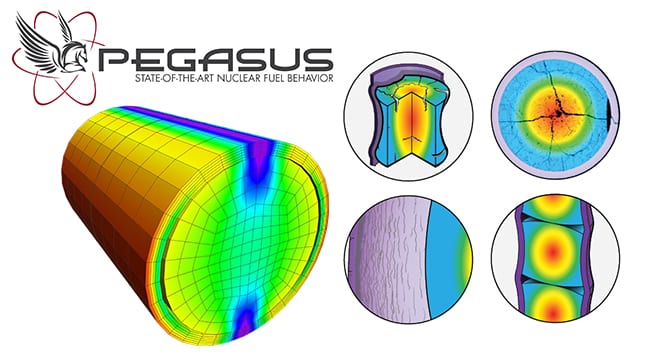
News & Views, Volume 53 | PEGASUSTM Nuclear Fuel Code
ADVANCED FUEL MODELING DEVELOPMENT STATUS
By: Bill Lyon
INTRODUCTION
The PEGASUS nuclear fuel behavior code features a robust 3D, finite element modeling (FEM) computational foundation capable of performing both thermo-mechanical and structural non-linear analyses within a highly versatile and customizable computational platform. The first applications of PEGASUS were for light water reactor (LWR) fuels and materials. Development work on PEGASUS has been extended to advanced fuel designs such as those proposed for Advanced Technology Fuel (ATF) LWR applications and Gen IV reactor designs, including gas and liquid metal-cooled reactors (GCRs and LMRs).
The versatility and adaptability of PEGASUS is key in enabling extensions to non-conventional operating environments, materials, fuel forms, and geometries.
LWR APPLICATIONS
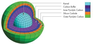
SiC Cladding
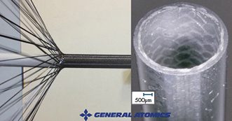
Figure 1. SiGA cladding is a multi-layered composite design composed of SiC fiber in a SiC matrix.
A project is underway to further the development and irradiation testing of a composite silicon carbide matrix as an ATF cladding material. This research is supported through a DOE Funding Opportunity award (DE-FOA-0002308) for the irradiation of a composite silicon-carbide (SiC) ceramic matrix material in an existing U.S. commercial LWR. This work is led by General Atomics – Electromagnetic Systems (GA-EMS) with Structural Integrity Associates (SIA) as a primary subcontractor. For this work, PEGASUS is being adapted to model monolithic and composite SiC manufactured by GA-EMS, SiGA [1], through the incorporation of proprietary material constitutive models. PEGASUS will then be used to provide independent test performance analyses aiding in the design of the irradiation vehicle and predicted material performance. The goal of the testing is to gather irradiation data under prototypic LWR operating conditions and to inform and confirm material performance models for the SiGA-based cladding. A follow-on activity is planned to evaluate the predicted performance compared to data gathered during the post-irradiation examination phase of the project.
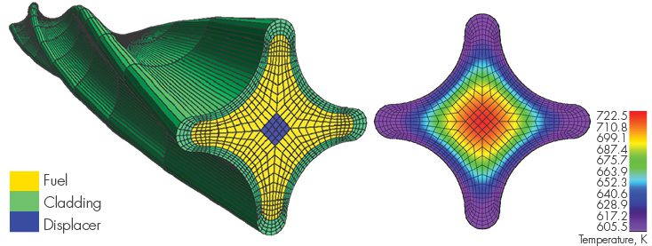
Figure 2. Lightbridge Fuel Design PEGASUS Models
Cruciform Metallic Fuel
An additional fuel concept that has been explored using PEGASUS is a cruciform, extruded metallic fuel design proposed by Lightbridge Corporation [2]. This fuel is characterized by a unique multi-lobed fuel cross-section and features a U-50Zr fuel composition. Recent work has been published on fabrication testing of this proposed fuel design by Pacific Northwest National Laboratory (PNNL) [3]. PEGASUS has been used previously to prototype 2D and 3D geometric models and meshes of Lightbridge fuel and to perform fundamental temperature and stress distributions for this fuel under prototypic LWR conditions. PEGASUS has specific modeling tools designed to facilitate “extruded” 3D fuel designs that automate the meshing of these geometries. More work in this area is planned as a proposal has recently been awarded under the DOE NEUP program (DE-FOA-0002732) funding a collaborative project led by Texas A&M University along with Lightbridge, NuScale, and Structural Integrity Associates, Inc. (SI) for modeling this type of fuel for application in a LWR SMR.
URANIUM METAL ALLOY FUELS FOR SODIUM-COOLED FAST REACTORS
The initial implementation of metallic alloy fuel and stainless-steel cladding material constitutive models for prototypic fast reactor fuel designs in PEGASUS has been completed. Material properties and behavioral models for U-Pu-Zr fuel and HT-9 (high Chromium, martensitic stainless steel) cladding have been added. Ongoing work includes the implementation of a gaseous swelling and fission gas release behavior model for U-Pu-Zr fuel, a Zr-redistribution model, and a fuel-cladding chemical interaction (FCCI) model that includes the effect on cladding wall thinning.
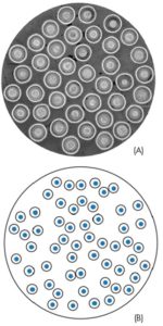
To test the implementation of these models, benchmark tests were prepared that provided comparative data for assessment of the models’ performance. Test cases were chosen from two experimental series irradiated in EBR-II: X430, a 37-pin hexagonal sub-assembly, and X441, a 61-pin bundle. These experiments were designed to test numerous fuel rod design variables and fuel response as a function of fuel alloy composition, smear density, plenum-to-fuel volume ratio, power, and coolant conditions [4]. The general experimental fuel rod design corresponds to the typical driver fuel configuration shown in Figure 3.
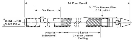
Figure 3. Typical EBR-II Mark-III or Mark-IIIA Fuel Element [5]
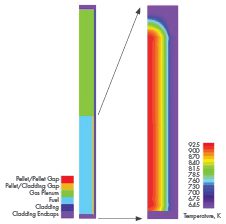
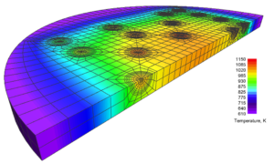
Figure 4. Left: 2D Computational Model of Rod DP2, Right: Temperature Contour Plot of the Fuel Stack Region for Rod DP21 at Peak Power (plenum region removed for detail)
An illustration of the model and selected results from the initial analysis of rod DP21, assembly X441 are shown in the figures above. Figure 4 provides a diagram of the computational model showing the primary components of the model and a plot of the temperature distribution throughout the fueled region of the rod at peak power. Figure 5 provides the radial temperature profile across the fuel rod from the center to the cladding outer surface at peak power near the end of the irradiation period. Temperatures vary from just ~900 K at the pellet center to ~650 K at the cladding surface. The temperature differential is fairly low at ~250 K, as would be expected from a high-conductivity metal fuel rod with a Na-bonded fuel cladding gap. These results are consistent with published experimental observations.
TRISO FUEL MODELING DEVELOPMENT
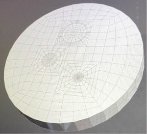
Several advanced fuel material models have been implemented specifically for TRISO fuel in PEGASUS, including thermal and mechanical models for UCO or UO2 kernels, PyC, SiC materials, and a fission gas release model for computing the release of gaseous fission products such as Xe and Kr. In addition to the standard 3D and 2D axisymmetric modeling FEM capabilities in the code, PEGASUS contains several unique tools designed specifically to support TRISO fuel modeling and analysis. These include a “spherical mesh object” tool that can automate the process of generating 2D/3D TRISO spheres, meshing them, and embedding them into a fuel matrix to allow modeling of individual TRISO kernels or fully encapsulated TRISO fuel forms. An example of models generated using the spherical mesh object tool is shown in Figure 6. The spherical mesh object capability is, to our knowledge, unique to PEGASUS and not found in any other fuel performance or general-purpose FEM code. PEGASUS also has a “reshape” function that can automate the process of meshing and modeling deformed TRISO particles to increase user efficiency. Figure 7 illustrates particle meshes that were created using the reshape meshing tool.
These modeling capabilities allow PEGASUS to be used to investigate very detailed mechanical and structural effects in TRISO fuel forms. For example, enabling the detailed analysis of the mechanical interaction between TRISO fuel layers explicitly examining the effects of cracking, debonding, and asphericity within whole or damaged particles.
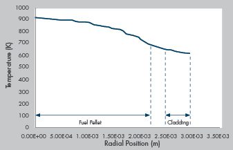
Figure 5. Radial Temperature Distribution Across the Fuel Rod Model at ~ 486 Days of Irradiation
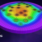
Planned future development work includes the integration of damage-mechanics modeling and fission product diffusion in the TRISO particle, fuel compact, ad matrix. One failure mode of particular interest that has been identified is cracking of the IPyC layer which propagates through the SiC outer layer. This can create a pathway for enhanced fission product release from the TRISO particle to the surrounding fuel matrix. This failure mechansim appears to occur when the buffer layer remains bonded to the IPyC layer providing the conditions for a synergistic mechanical and chemical failure mechanism that combines cracking, stress concentration, and chemical corrosion (localized Pd-induced corrosion in the SiC [6]. This failure mode is of interest because it can have a strong impact on fuel source term determination for operational TRISO fuel.
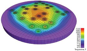
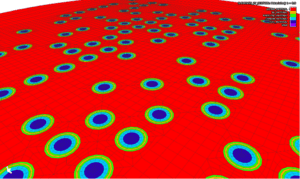
Figure 6. Temperature distribution in a cross-section of a 3D slab of a TRISO compact matrix model with a “sparse”, random kernel distribution under prototypic gas-cooled reactor conditions. (Generated using the “spherical mesh object” tool.)
SUMMARY
PEGASUS is an advanced analysis tool developed for industry applications that can provide a complimentary and independent capability for nuclear fuel performance. Recent development work on PEGASUS has focused on expanding the applicability of the code to the advanced fuel (ATF) and advanced reactor arena. Future development is planned for PEGASUS that will continue along multiple avenues with an emphasis on advanced fuels and specific thermo-mechanical issues within the industry, such as deterministic failure model development. One example of this is the aforementioned Pd-induced failure mechanism identified for TRISO fuel. SI is actively seeking partners within the advanced fuel community to collaborate with on this work and would welcome inquiries and proposals for expanded application of PEGASUS.
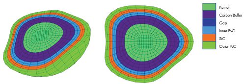
Figure 7. Deformed 3D TRISO particle meshes generated using the “reshape” function tool in PEGASUS.
References
- C. P. Deck et al., Overview of General Atomics SiGA™ SiC-SiC Composite Development for Accident Tolerant Fuel, Transactions of the American Nuclear Society, Vol. 120, Minneapolis, Minnesota, June 9–13, 2019.
- J. Malone, A. Totemeier, N. Shapiro, and S. Vaidyanathan, Lightbridge Corporation’s Advanced Metallic Fuel, Nuclear Technology, Vol 180, Dec. 2012.
- Z. Huber and E. Conte, Casting and Characterization of U-50Zr, PNNL-33873, Pacific Northwest National Laboratory, Richland, Washington 99354, Jan. 2023.
- C. E. Lahm, J. F. Koenig, R. G. Pahl, D. L. Porter, and D. C. Crawford, “Experience with Advanced Driver Fuels in EBR-II,” J. Nucl. Mat. 204 (1993) 119-123.
- G. L. Hofman, M. C. Billone, J. F. Koenig, J. M. Kramer, J. D. B. Lambert, L. Leibowitz, Y. Orechwa, D. R. Pedersen, D. L. Porter, H. Tsai, and A. E. Wright. Metallic fuels handbook, Technical Report ANL-NSE-3, Argonne National Laboratory, 2019.
- J.D Hunn, C.A. Baldwin, T.J. Gerzak, F.C. Montgomery, R.N. Morris, C.M. Silva, P.A Demkowicz, J.M. Harp, and S.A. Ploger, Detection and Analysis of Particles with Failed SiC in AGR-1 Fuel Compacts, Nuclear Engineering and Design, April 2016.

 Structural Integrity Associates is participating in a Department of Energy (DOE) Integrated Research Projects (IRP) program focused on storage and transportation of used nuclear fuel (UNF). The project, entitled Cask Mis-Loads Evaluation Techniques, was awarded to a university-based research team in 2016 under the DOE Nuclear Fuels Storage and Transportation (NFST) project. The team is led by the University of Houston (U of H) and includes representatives from the University