News and Views, Volume 54 | Monticello Nuclear Generating Plant – BioShield Evaluation

By Livia Costa-Mello, Shari Day, and Dan Denis

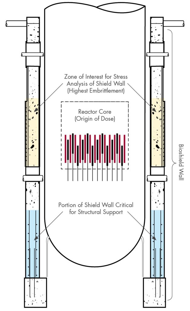
Figure 1. Example of RPV and Bioshield showing areas of interest for evaluation.

Background
Many U.S. nuclear plants are completing license renewal (LR) activities to extend their operating life.  The initial LR application extends operating licenses from 40 to 60 years; the subsequent renewal (SLR) further extends this from 60 to 80 years.  As part of the LR/SLR application process, utilities must demonstrate that they have accounted for a variety of potential aging mechanisms that may take place over the ensuing operating period.  One such mechanism is the loss of strength and/or ductility due to long-term exposure to high levels of radiation.  This includes the reactor pressure vessel (RPV) and primary system piping but also extends to support structures (steel/concrete) in the vicinity of the RPV.

Xcel Energy submitted their SLR application for the Monticello Nuclear Generating Plant in January 2023.  Constructed in the 1960s, Monticello is the oldest operating boiling water reactor (BWR) in the U.S. fleet and will reach 60 years of operation in 2030.  As part of the Nuclear Regulatory Commission’s (NRC’s) standard review plan (SRP) for SLR applications1, detailed evaluations are recommended for steel and concrete structures which are predicted to exceed certain established thresholds of irradiation dose.  This includes the biological shield wall (also referred to as the “bioshield” or “sacrificial shield”), a large concrete and steel structure that surrounds the RPV  whose primary purpose is to shield workers and equipment from high levels of neutron and gamma radiation.  In addition, the bioshield provides support for other critical components.

Xcel contracted SI to perform an evaluation of the Monticello bioshield in support of its SLR application.  Initially, SI assessed embrittlement of the concrete and steel in accordance with the methodology in NUREG-15092 .  Following questions posed by the NRC reviewers, additional clarifications were requested regarding plant-specific materials, justification of gamma heating parameters, and inclusion of weld residual stresses.  SI performed separate heat transfer and fracture mechanics analyses to address these inquiries.  This article summarizes the approach and results of this first-of-a-kind evaluation.

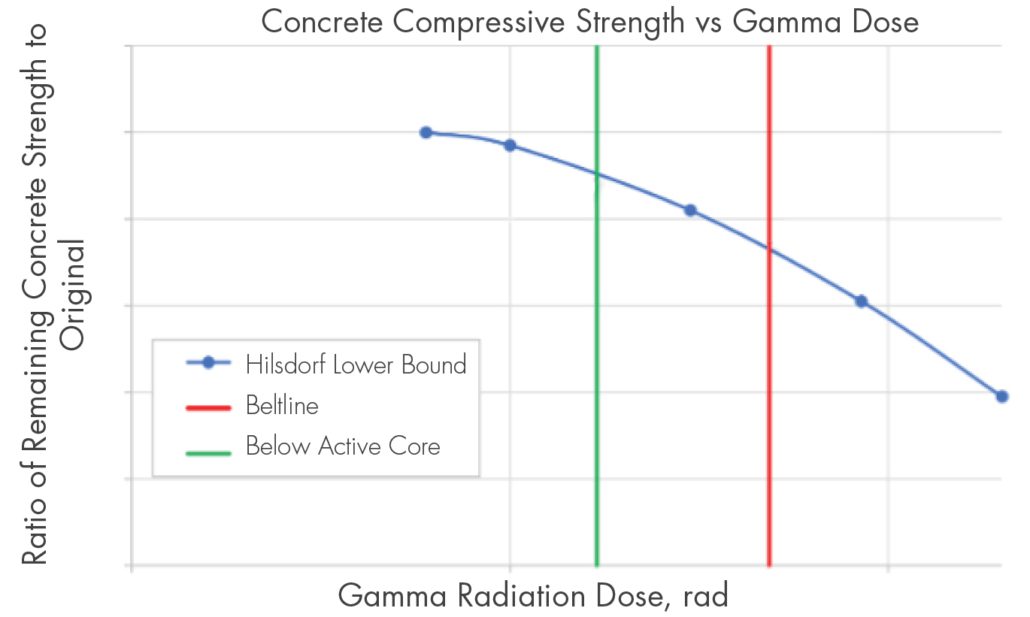
Figure 2. Typical Reduction in concrete strength due to irradiation.

Assessment of Bioshield Concrete Structure
As illustrated in figure 1, the portion of the shield wall that is critical for support purposes is near the bottom of the RPV, well below the active core.  However, in accordance with the SRP, the concrete within this region is evaluated for irradiation-induced capacity reductions in accordance with methodology outlined within related EPRI reports.  Both neutron and gamma dose were evaluated in accordance with NUREG-2192 guidelines, along with expected operating temperatures experienced by the concrete.

Radiation exposure levels for the Monticello bioshield at the end of the SLR operating period were computed via separate third-party analysis.  The computed neutron fluence was less than the threshold for potential concrete damage, rendering it unnecessary to evaluate this item, but the computed gamma dose exceeded the potential damage threshold.  Therefore, SI performed a detailed study to extrapolate the gamma exposure and any associated loss of strength for the load-bearing portion of the bioshield wall.  The evaluation compared published lower-bound strength values from literary sources to the fluence values obtained from which a conservative factor on reduction in structural capacity was determined.

SI performed a detailed set of structural calculations to benchmark the original design basis analysis against the pertinent code of construction, ACI 318-63.  These calculations were repeated for the predicted reduction in strength, and for all locations the predicted loads (or “demand”) were less than the available capacity.  Thus, the structural portion of the bioshield wall was assessed to be acceptable for extended operation through the SLR period.

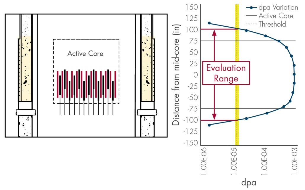
Figure 3. Dpa Variation as a function of Distance from Core Mid-Plane, Adjusted to Bounding Dpa for Shield Wall

Assessment of Bioshield Steel Liner
SI performed an assessment of the steel liner plates on either side of the bioshield wall, in accordance with NUREG-1509.  The evaluation began with identifying the region of the bioshield subject to the highest radiation exposure.  Comparing the elevation of the active core to the predicted distribution of neutron irradiation, the region of interest was determined to be ±100 inches above/below the core centerline.  In this region, the only structural steel elements are the WF27x177 columns and the 1-¾” and ¼” thick liner plates.

For the indicated region, the effect of irradiation on the shift in ductile to brittle fracture transition temperature (known as “nil ductility temperature” or NDT) was evaluated.  An NDT shift is calculated by referencing the irradiation at various elevations against criteria from NUREG-1509; this value is added to the initial NDT to compute an adjusted NDT.

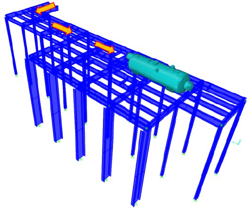
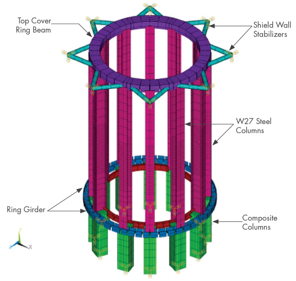
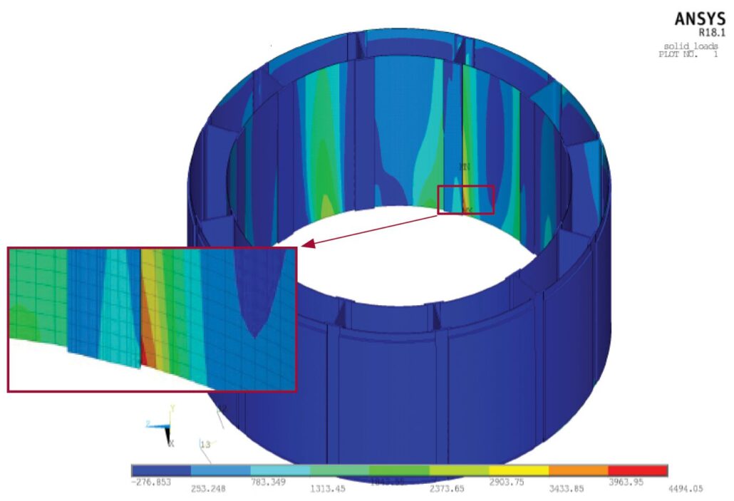
ANSYS was used to develop a finite element model of key structural members for subsequent analyses.  To benchmark the original design basis analysis, the model was initially developed using only the columns, girders, and stabilizers, after which all design basis loads were applied.  However, the results from this model were observed to exhibit significant displacement of the steel columns due to weak axis bending.  Therefore, SI developed an enhanced model for the key embrittled region to include the liner plates.  The maximum principal stresses from this enhanced model were demonstrated to be less than the 6 ksi operational stress limit in NUREG-1509.  Therefore, the steel portion of the Monticello bioshield was determined to remain structurally sound for the period of SLR extended operation.

Figure 4. Frame Model of Shield Wall Space Frame

Upon initial NRC review of the concrete and structural evaluations, additional questions were raised regarding NRC desired modifications to the NUREG-1509 methodology for extended SLR operation.  The primary focus of these questions related to conservatism of the analyses when accounting for Monticello-specific properties, such as gamma heating of the concrete and impacts of weld residual stresses.  Accordingly, SI developed a plant-specific heat transfer evaluation, and used those results to perform a fracture mechanics analysis of the stress state in the limiting beltline region.

Bioshield Heat Transfer Analysis
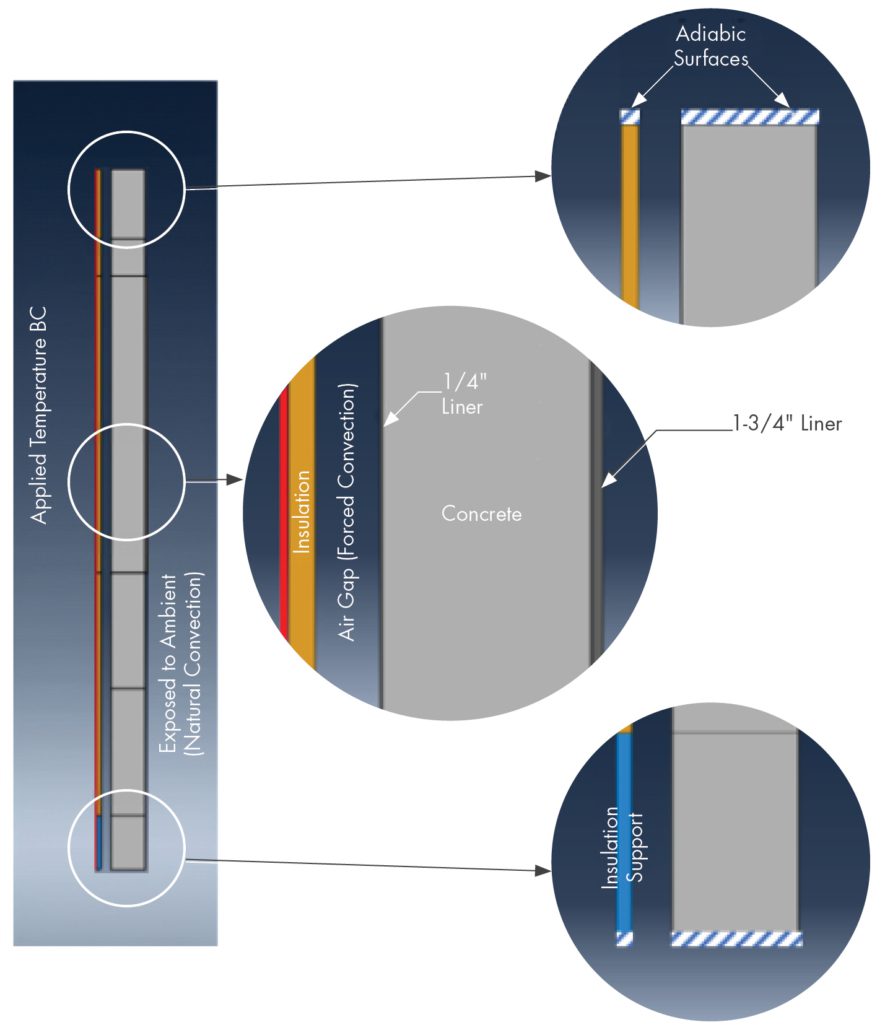
During NRC review of the steel and concrete analyses described in the prior sections, questions were raised regarding the potential for additional degradation of the concrete due to extended exposure to high temperatures and gamma-induced heating.  To address these questions, SI developed a heat transfer model of the bioshield, accounting for RPV insulation, the annular air gap, and conduction through both liner plates and the concrete.  Calculations were performed both by hand and using an axisymmetric model within Abaqus.

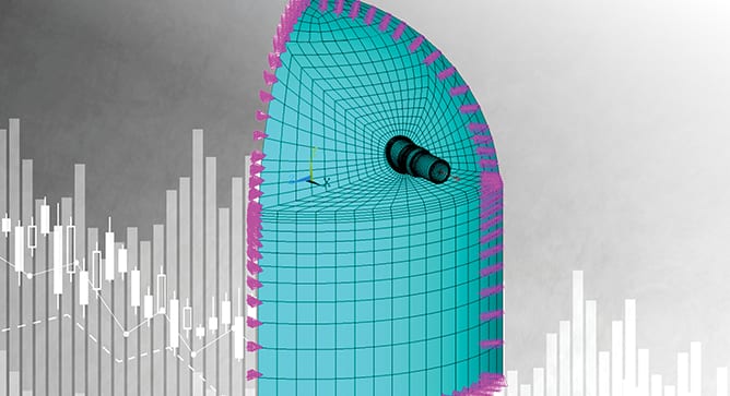
Figure 5. Detailed stress analysis results for critical region of bioshield.

The maximum temperature within the concrete portion of the bioshield was calculated to be below a 150 °F threshold value from the American Concrete Institute (ACI) for nuclear safety-related structures.  The added temperature due to gamma radiation heating was estimated as less than 1.5 °F. Therefore, the bioshield was determined to be acceptable for long-term thermal exposure.  The temperatures during operation do induce additional thermal expansion stresses in the hoop direction on the outer liner.  Using the heat transfer model and application coefficients of expansion, these stresses were estimated to be less than 1 ksi, which are judged to be minimal given that primary loads on these members are in the bioshield-axial direction.  Based on these results, there is no concern for thermally induced damage of the Monticello bioshield over the course of the SLR extended operating period.

Bioshield Fracture Mechanics Evaluation
NUREG-1509 includes an evaluation of a postulated flaw in structural steel members, in accordance with the fracture toughness approach in ASME Code, Section XI, Appendix G.  For Monticello, the bioshield is constructed of ASME A36 steel, which was considered for computation of the NDT temperature, resulting in an allowable fracture toughness based on the ASME code. However, when considering industry literature and prior SLR evaluations, this value was conservatively reduced for the Monticello Evaluation. The fracture mechanics evaluation from NUREG-1509 was reproduced, using inputs from the steel liner FEA and bioshield heat transfer analysis.  The resulting analysis demonstrated sufficient margin between the applied stress intensity and conservative allowable fracture toughness, confirming that the Monticello bioshield would remain intact with no potential for brittle fracture even in the event of a postulated flaw.

Figure 6. Simplified heat transfer model for bioshield.

Conclusions
SI completed a first-of-a-kind evaluation of the Monticello bioshield, assessing long-term adequacy of the structural steel and concrete with exposure to irradiation and thermal effects.  The analysis introduced reasonable inputs in place of overly conservative assumptions and considered multiple potential aging mechanisms in order to comprehensively assess future conditions.  The results of the evaluation were accepted by the NRC, demonstrating a success path to perform similar evaluations for other sites pursuing LR/SLR.  These analyses are unique on a case-by-case basis, as each plant’s design, construction, and operational history will result in different regions and/or components being included in the evaluation.


References

  1. U.S. NRC Report NUREG-2192, “Standard Review Plan for Review of Subsequent License Renewal Applications for Nuclear Power Plants,” July 2017.
  2. U.S. NRC Report NUREG-1509, “Radiation Effects on Reactor Pressure Vessel Supports,” May 1996.


Get News & Views, Volume 54

News and Views, Volume 55 | UPDATE: Encoded Phased Array Ultrasonic Examination Services for Cast Austenitic Stainless Steel (CASS) Piping Welds in Pressurized Water Reactor (PWR) Coolant Systems

By:  John Hayden and Jason Van Velsor

Our initial article on this topic in News & Views, Volume 531 describes the challenges imposed by cast austenitic stainless steel (CASS) materials and the development of our CASS UT Examination solution. At the time of the prior article’s publication, SI was also conducting examinations of numerous CASS piping specimens. This article provides details of both that performance demonstration and the results of those examinations.

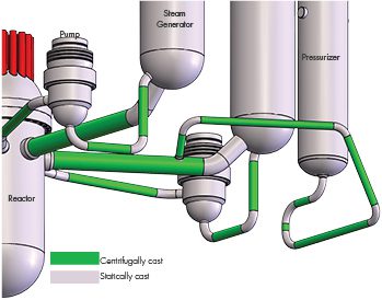
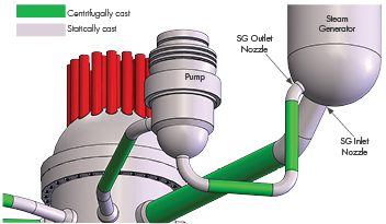
TYPICAL CASS PIPING WELD LOCATIONS IN PWR REACTOR COOLANT SYSTEMS
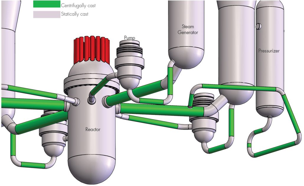
Figure 1 illustrates the presence of CASS piping components, both statically and centrifugally cast, in the primary Reactor Coolant Systems of many U.S. PWR plants. Other PWR plant designs also contain CASS components, albeit in fewer locations and only in the form of short spool piece segments, usually for reactor coolant pumps and safety injection system safe ends.

Figure 1. Locations of CASS piping components, both statically and centrifugally cast, in primary Reactor Coolant Systems of many U.S. PWR plants

REGULATORY BASIS FOR CASS EXAMINATION CAPABILITY
ASME Section XI Code Case N-824, which was approved by the NRC in 2019, provides specific direction and requirements for ultrasonic examination of welds joining CASS components. N-824 was incorporated into Section, XI, Appendix II, Supplement 2 in the 2015 Code edition. The NRC has stated (10CFR50.55a, 07/18/2017) that with use of the aforementioned N-824 methodology “Licensees will be able to take full credit for completion of the § 50.55a required in-service volumetric inspection of welds involving CASS components.” SI’s procedure development and demonstration were therefore based on these requirements.

ULTRASONIC TECHNIQUE PERFORMANCE DEMONSTRATION
Though not required by the ASME Code, SI conducted a performance demonstration of our CASS UT system at our facility in Huntersville, NC. Using CASS piping system specimens on loan from the EPRI NDE Center, SI successfully validated our ultrasonic examination system capabilities as follows.

Ultrasonic Procedure – SI’s CASS ultrasonic examination procedure is fully compliant with ASME Section XI Code documents, and NRC-imposed technical approval conditions. The procedure has also been optimized with many insights gained from our laboratory experiences while examining EPRI-owned CASS piping specimens.

Ultrasonic Equipment – The ultrasonic system components required by Code have been designed and fabricated by SI or purchased, including the following:

  • Ultrasonic instrumentation capable of functioning over the entire prescribed ranges of examination frequencies. The standard examination frequency range extends from low-frequency, 500 KHz operation for CASS pipe welds > 1.6” Tnom and 1.0 MHz for CASS pipe welds ≤ 1.6” Tnom
  • Transducer arrays were employed to meet the physical requirements of frequency and aperture size capable of generating the Code-prescribed wave mode, examination angles, and focal properties.
  • An assortment of wedge assemblies were designed and fabricated then mated with transducer arrays to provide effective sound field coupling to the CASS components being examined.

Data encoding options necessary to acquire ultrasonic data given the expected range of component access and surface conditions are available. The encoding options include:

  • A fully-automated scanning system capable of driving the relatively large and heavy 500KHz phased array probes. This system was used during our laboratory examinations of CASS piping specimens.
  • A manually driven encoding system — a proven, field-worthy tool — which may be employed in locations where fully automated systems cannot be used because of access restrictions.

Examination Personnel – The challenges that exist with the examination of CASS piping welds warrant a comprehensive program of specialized, mandatory training for personnel involved with CASS examinations. This training includes descriptions of coarse grain structures, their effect on the ultrasonic field, the expected ultrasonic response characteristics of metallurgical and flaw reflectors, and the evaluation of CASS component surface conditions.

Additionally, SI’s ultrasonic examination personnel are thoroughly trained and experienced in all elements of encoded phased array ultrasonic data acquisition and analysis in nuclear plants and hold multiple PDI qualifications in both manual and encoded phased array DM weld techniques.

EPRI CASS PIPING SPECIMENS
The EPRI CASS pipe specimens, their outside diameter (OD) and thickness dimensions, and butt weld configurations examined by SI are described below.

12.75″ OD, 1.35″ Tnom SPECIMENS
Three pipe-to-pipe specimens representative of piping found in pressurizer surge and safety injection applications were examined. Each of these specimens had the weld crown ground flush.

Figure 2. Schematic of 12.75” OD, 1.35” Tnom CASS specimens.

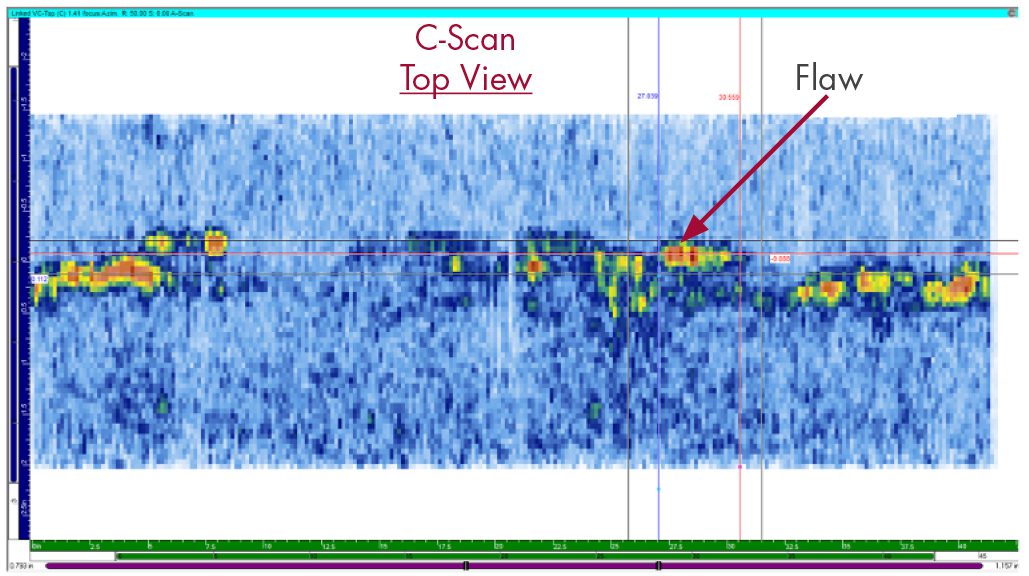
Figure 3, Figure 4, and Figure 5 present examples of ultrasonic data images of a flaw detected in a 12.75” OD pipe-to-pipe tapered specimen.

Figure 3. Representative ultrasonic C-Scan data image from 12.75” OD, 1.35” Tnom specimen.

The C-Scan is a 2-D view of ultrasonic data displayed as a top (or plan) view of the specimen. The horizontal axis is along the pipe circumference, and the vertical axis is along the pipe axis or length.

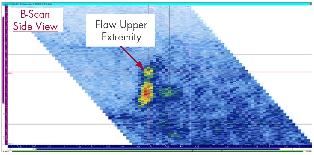
Figure 4. Representative ultrasonic B-Scan data image from 12.75” OD, 1.35” Tnom specimen.

The B-Scan is a 2-D view of ultrasonic data displayed as a side view of the specimen. The angular projection of the data is displayed along the examination angle. The horizontal axis is along the pipe axis, and the vertical axis is along the pipe thickness.

Figure 5. Representative ultrasonic D-Scan data image from 12.75” OD, 1.35” Tnom specimen.

The D-Scan is a 2-D view of ultrasonic data displayed as an end view of the specimen. The horizontal axis represents the pipe circumference, and the vertical axis is along the pipe thickness.

28″ OD, 2.0″ Tnom SPECIMENS
Four pipe-to-pipe specimens representative of piping found in reactor coolant loops were examined. Each of these specimens had the weld crown intact and left in place.

Figure 6. Schematic of 28” OD, 2.0” Tnom CASS specimens.

Figure 7, Figure 8, and Figure 9 present examples of ultrasonic data images of a flaw detected in a 28” OD pipe-to-pipe tapered specimen.

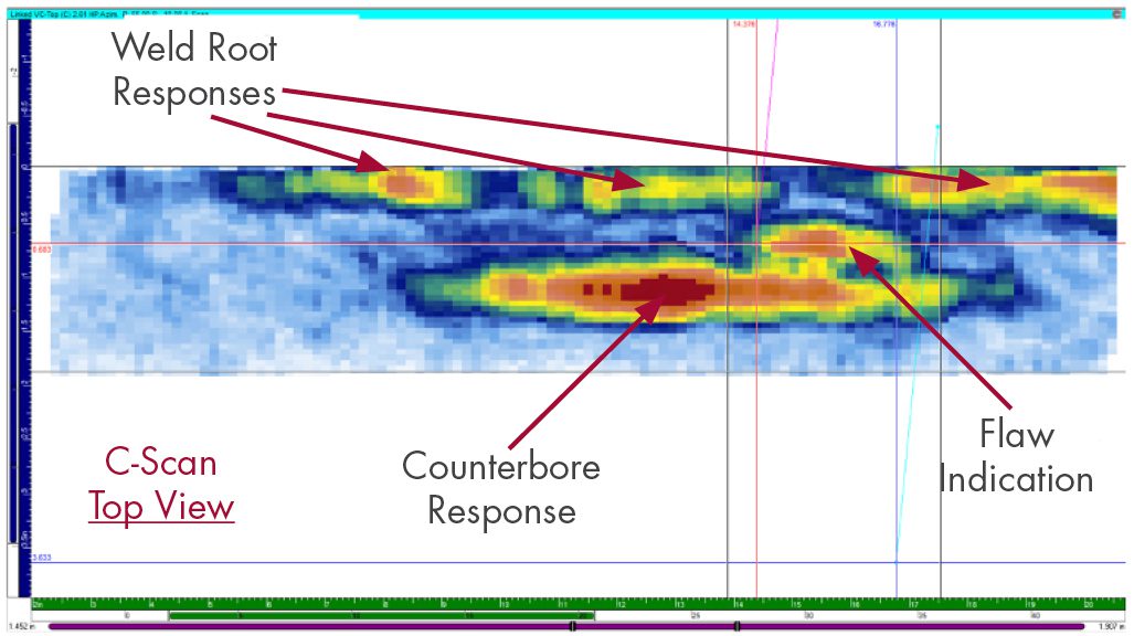
Figure 7. Representative ultrasonic C-Scan data image from 28” OD, 2.0” Tnom specimen.

The C-Scan is a 2-D view of ultrasonic data displayed as a top (or plan) view of the specimen. The horizontal axis is along the pipe circumference, and the vertical axis is along the pipe axis or length.

Note the ability of our UT data acquisition equipment and data analysis techniques to resolve, discriminate, and identify inside surface geometric conditions (weld root and pipe counterbore), along with detecting and sizing the flaw indication. Also, note the excellent signal-to-noise ratio achieved.

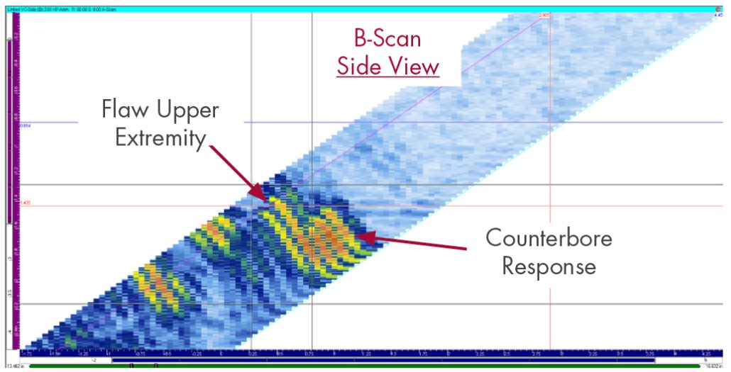
Figure 8. Representative ultrasonic B-Scan data image from 28” OD, 2.0” Tnom specimen.

The B-Scan is a 2-D view of ultrasonic data displayed as a side view of the specimen. The angular projection of the data is displayed along the examination angle. The horizontal axis is along the pipe axis or length. The vertical axis is along the pipe thickness.

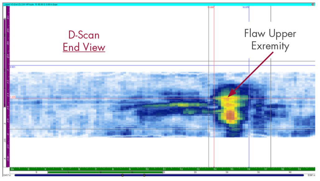
Figure 9. Representative ultrasonic D-Scan data image from 28” OD, 2.0” Tnom specimen.

The D-Scan is a 2-D view of ultrasonic data displayed as an end view of the specimen. The horizontal axis is along the pipe circumference, and the vertical axis is along the pipe thickness.

28″ to 29″ OD, 2.0″ to 2.5″ Tnom TAPERED WELD SPECIMENS
Four pipe-to-pipe specimens, with tapered weld surfaces representative of piping found in reactor coolant loops were examined.

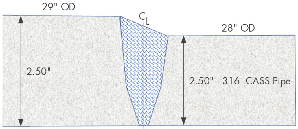
Figure 10. Schematic of 28” to 29” OD, 2.0” to 2.5” Tnom CASS specimens.

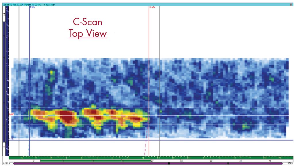
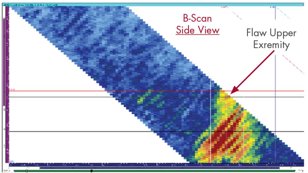
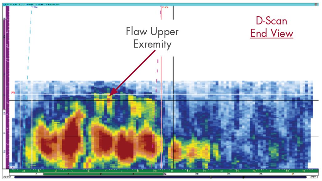
Figures 11, 12, and 13 present examples of ultrasonic data images of a flaw detected in a 28” OD to 29” OD pipe-to-pipe tapered specimen.

Figure 11. Representative ultrasonic C-Scan of a 28” to 29” OD, 2.0” to 2.5” Tnom pipe-to-pipe, with tapered weld surfaces.

The C-Scan is a 2-D view of ultrasonic data displayed as a top (or plan) view of the specimen. The horizontal axis is along the pipe circumference, and the vertical axis is along the pipe axis, or length.

Figure 12. Representative ultrasonic B-Scan of a 28” to 29” OD, 2.0” to 2.5” Tnom pipe-to-pipe, with tapered weld surfaces.

The B-Scan is a 2-D view of ultrasonic data displayed as a side view of the specimen. The angular projection of the data is displayed along the examination angle. The horizontal axis is along the pipe axis or length. The vertical axis is along the pipe thickness.

Figure 13. Representative ultrasonic D-Scan of a 28” to 29” OD, 2.0” to 2.5” Tnom pipe-to-pipe, with tapered weld surfaces.

The D-Scan is a 2-D view of ultrasonic data displayed as an end view of the specimen. The horizontal axis is along the pipe circumference, and the vertical axis is along the pipe thickness.

SUMMARY OF DATA ANALYSIS RESULTS
Documentation was provided for each EPRI specimen, which contains flaw location, length, and through-wall size to permit the comparison of UT data acquisition and analysis processes to actual flaw conditions.

All of the 23 circumferential flaws in the eleven EPRI specimens were detected. The ultrasonic examination and data analysis techniques achieved flaw location and length sizing RMS errors, which are within acceptance standards of the following ASME Section XI, Appendix VIII Qualification Supplements:

  • Supplement 2, Qualification Requirements for Wrought Austenitic Stainless Steel Piping
  • Supplement 10, Qualification Requirements for Dissimilar Metal Piping

Excellent signal-to-noise ratios were observed for all detected flaws.

For all flaws, the measured length achieved sizing RMS errors within the acceptance standards of the above Appendix VIII supplements.

For specimens with welds ground flush and for all specimens with sufficient access to interrogate the entire through-wall extent of flaws, SI’s technique achieved through-wall sizing RMS errors within the acceptance standards of the above Appendix VIII supplements.

To be clear, the examination of the EPRI CASS specimens does not meet the rigor of Appendix VIII, Supplement 9 qualification because the industry’s (PDI Program) for CASS piping welds is still in preparation. The comparison to Appendix VIII acceptance standards is provided solely as a means to describe the achieved flaw detection and sizing capabilities in CASS material in terms of already established PDI qualifications. Ongoing examination of additional CASS specimens will strengthen already existing ultrasonic examination capabilities and experience.

CONCLUSIONS
The CASS piping welds in many PWR plants provide numerous and complicated challenges to their effective ultrasonic examinations. Most, if not all, CASS RCS piping welds have not been subjected to a meaningful and effective volumetric examination since radiography was conducted during plant construction.  SI’s newly-demonstrated ultrasonic examination procedure for CASS delivers a demonstrated, Code-compliant, meaningful, and effective solution that provides full credit for completion of in-service volumetric inspection per § 50.55a.

References

  1. News and Views, Volume 53, October 2023, “Encoded Phased Array Ultrasonic Examination Services for CASS Piping Welds In PWR Reactor Coolant Systems”
  2. ASME Section XI Code Case N-824, “Ultrasonic Examination of Cast Austenitic Piping Welds from the Outside Surface”
  3. ASME B&PV Code, Section XI, 2015 Edition and later editions

Download PDF

News & Views, Volume 53 | Encoded Phased Array Ultrasonic Examination Services for Cast Austenitic Stainless Steel (CASS) Piping Welds

IN PRESSURIZED WATER REACTOR (PWR) COOLANT SYSTEMS

By:  John Hayden and Jason Van Velsor

The CASS piping welds present in many PWR plants provide numerous and complicated challenges to their effective ultrasonic examinations. To this point, a viable ultrasonic examination solution for the inspection of these piping components, as required by ASME Code Section IX,  had previously not been available. By leveraging our technical expertise in materials, technology development, and advanced NDE deployment, Structural Integrity Associates, Inc (SI) has developed a new system that will provide a meaningful solution for the examination of CASS piping components. The result of this program will be the first commercial offering for the volumetric examination of CASS components in the nuclear industry.

BACKGROUND INFORMATION
ASME Section XI Class 1 RCS piping system welds fabricated using CASS materials pose serious and well-understood challenges to their effective ultrasonic examination. For decades, utilities and regulators have struggled with the administrative and financial burdens of Relief Requests, which were, and still are, based on the inability to perform meaningful volumetric examinations of welds in CASS components. 

Many years of futility and frustration may have fostered the belief that technology allowing effective and meaningful examination of CASS materials would never be achievable. This is no longer the case.

The failure mechanism for CASS material occurs through the loss of fracture toughness due to thermal aging embrittlement. The susceptibility of CASS material to thermal aging embrittlement is strongly affected by several factors, primary of which are system operating time and temperature, the casting method used during component manufacture, and molybdenum and ferrite content. In addition to the existing ASME Section XI requirements for the examination of welds in CASS materials, the susceptibility to thermal aging embrittlement drives the requirement for additional examinations (including ultrasonic examinations) as directed by several NRC-published NUREGs required for plant license renewal. The existence of a viable, effective examination capability for CASS materials plays a very important part in both currently required Inservice Inspections (ISI) and plant license renewal.

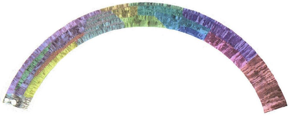
Figure 1. An example of the widely-varying microstructure of a centrifugally cast piping segment. False-color imaging is used to aid visualizing grain variations. (Image from NUREG/CR-6933 PNNL-16292)

CASS MATERIAL PROPERTIES AND EFFECT ON ULTRASONIC EXAMINATION
Metallurgical studies have revealed that the microstructure of CASS piping can vary drastically in the radial (through-wall) direction, as well as around the circumference and along the length of any given piping segment. Large and small equiaxed, columnar and mixed (combinations of equiaxed and columnar grains), and banding (layers of substantially different grain structures) are commonly observed in CASS piping materials. None of these conditions favor the performance of effective ultrasonic examinations.

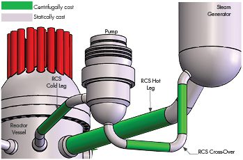
Figure 2. PWR RCS Major Components

The very large and widely varying types (equiaxed, columnar, and randomly mixed), sizes and orientations of the anisotropic grains in CASS material are very problematic. Anisotropic is defined as an object or substance having a physical property that has a different value when measured in different directions. Such physical properties strongly affect the propagation of ultrasound in CASS material by causing severe attenuation (loss of energy through beam scattering and absorption), beam redirection, and unpredictable changes in ultrasonic wave velocity. These factors are responsible for the inability of ultrasonic examination to completely and reliably interrogate the Code-required volume (inner 1/3 Tnom) of welds in CASS piping material. Interestingly, CASS materials less than 1.6” Tnom (Pressurizer Surge Piping) can be effectively examined, while CASS materials over 2.00” (Main RCS Coolant Loop Piping) are less effectively examined.  Consequently, an ASME Section XI, Appendix VIII qualification program for CASS piping components has not been established and remains in the course of preparation. Nonetheless, ASME Section XI requirements to conduct inservice examinations of RCS piping welds fabricated from CASS components remain fully in force.

ASME CODE ACTIONS AFFECTING CASS PIPING EXAMINATIONS
ASME Section XI Code Case N-824, “Ultrasonic Examination of Cast Austenitic Piping Welds From the Outside Surface,” was approved by ASME in October 2012 and by the NRC in October 2019. This Code Case provides the first approved direction for the ultrasonic examination of welds joining CASS piping components. The ASME B&PV Code, Section XI, 2015 Edition, incorporates Code Case N 824 into Mandatory Appendix III in the form of Mandatory Supplement 2. To date, these two ASME Section XI Code documents remain the sole sources approved by ASME and NRC that provide specific direction for the examination of CASS RCS piping system welds and, therefore, form the foundation of SI’s approach for the development of our CASS ultrasonic examination solution.

SI’S CASS PROGRAM DESCRIPTION
SI is developing the industry’s most well-conceived and capable ultrasonic system for the examination of welds in CASS piping components. To accomplish this objective, SI has drawn upon our internal knowledge and experience, supplemented by a careful study of numerous authoritative bodies of knowledge relating to the examination of CASS components. The development of the SI examination system has been guided by both SI’s industry-leading 17 years of experience conducting phased array examinations in nuclear power plants and the knowledge acquired through the careful study of the topical information contained within industry-recognized publications. These published results of extensive industry research provided both guidance for the selection of phased array system components and CASS-specific material insights that strengthen the technical content of our Appendix III-based procedure. 

Figure 3. RCS Coolant Pump and Crossover Piping

CASS PROGRAM ELEMENTS
SI believes that the procedure, equipment and personnel featured in this program will be equivalent or superior to those that will form the industry-consensus approach for CASS ultrasonic examinations needed to successfully achieve Appendix VIII, (future) Supplement 9, “Qualification Requirements for Cast Austenitic Piping Welds.”

Ultrasonic Procedure – SI has crafted an ultrasonic examination procedure framework that is fully compliant with ASME Section XI, Mandatory Appendix III, Supplement 2, along with referenced Section XI Appendices as modified by the applicable regulatory documents.

Ultrasonic Equipment – SI has acquired and assembled the ultrasonic system components required by Code Case N-824 and Appendix III, Supplement 2, which includes the following:

  • Ultrasonic instrumentation capable of functioning over the entire expected range of examination frequencies. The standard examination frequency range extends from low-frequency, 500 KHz operation for RCS main loop piping welds through 1.0 MHz for pressurizer surge piping. 

SI has designed and acquired additional phased array transducers that meet the physical requirements of frequency, wave mode, and aperture size and are capable of generating the prescribed examination angles with the required focal properties. SI has designed and fabricated an assortment of wedge assemblies that will be mated with our phased array probes to provide effective sound field coupling to the CASS components being examined. SI’s wedge designs consider the CASS pipe outside diameter and thickness dimensions and employ natural wedge-to-material refraction to assure optimal energy transmission and sound field focusing.

SI also possesses several data encoding options that are necessary to acquire ultrasonic data over the expected range of component access and surface conditions. The encoding options will include:

  • Fully-automated scanning system, capable of driving the relatively large and heavy 500KHz phased array probes
  • The SI-developed Latitude manually-driven encoding system, which has been deployed during PDI-qualified dissimilar metal DM weld examinations in nuclear power plants

    Figure 4. Steam Generator Details

Examination Personnel – SI’s ultrasonic examination personnel are thoroughly trained and experienced in all elements of encoded ultrasonic data acquisition and analysis in nuclear plants. SI’s examiners have a minimum of 10 years of experience and hold multiple PDI qualifications in manual and encoded techniques. SI recognizes the challenges that exist with the examination of CASS piping welds and has developed a comprehensive program of specialized, mandatory training for personnel involved with CASS examinations. This training includes descriptions of coarse grain structures, their effect on the ultrasonic beam, and the expected ultrasonic response characteristics of metallurgical and flaw reflectors, as well as the evaluation of CASS component surface conditions.

ULTRASONIC TECHNQUE VALIDATION
Although not required by the ASME Code, SI has arranged for access to CASS piping system specimens from reputable sources to validate the efficiency of our data acquisition process and the performance of our ultrasonic examination techniques. The specimens represent various pipe sizes and wall thicknesses and contain flaws of known location and size to permit the validation and optimization of SI’s data acquisition and analysis processes. SI will thoroughly analyze, document, and publish the results of our system performance during the examination of the subject CASS specimens.

Figure 5. Pressurizer and Surge Line Details

CASS PIPING SYSTEM APPLICATIONS
Typical CASS Piping Weld Locations in PWR Reactor Coolant Systems
The following graphic illustrates the location and extent of CASS materials in the RCS of many PWR plants.

RCS Main Loop Piping Welds: This portion of the RCS contains large diameter butt welds that join centrifugally cast stainless steel (CCSS) piping segments to statically cast stainless steel (SCSS) elbows and reactor coolant pump (RCP) casings. RCS main loop piping includes the following subassemblies:

  • Hot leg piping from the Reactor Vessel Outlet to the SG Inlet
  • Cross-over piping from the SG Outlet to the RCP Inlet
  • Cold leg piping from the RCP Outlet to the RPV Inlet

Steam Generator Inlet / Outlet Nozzle DM Welds: These terminal end DM butt welds are present in PWR plants, both with and without safe ends between the SCSS elbows and the ferritic steel nozzle forgings. 

Pressurizer Surge Piping Welds: This portion of the RCS contains a series of butt welds fabricated using CCSS piping segments to SCSS elbows between the Pressurizer Surge nozzle end and the Hot Leg Surge nozzle. 

SUMMARY
The CASS piping welds present in many PWR plants provide numerous and complicated challenges to their effective ultrasonic examinations. SI’s new CASS ultrasonic examination system will provide a new and meaningful solution.

PROJECT TIMELINE
SI is working to complete the development, integration and capability demonstrations of the CASS ultrasonic examination system described in this document for limited (emergent) fall 2023 and scheduled deployments beginning in spring 2024.

Get News & Views, Volume 53

News & Views, Volume 53 | PEGASUSTM Nuclear Fuel Code

ADVANCED FUEL MODELING DEVELOPMENT STATUS

By:  Bill Lyon

INTRODUCTION
The PEGASUS nuclear fuel behavior code features a robust 3D, finite element modeling (FEM) computational foundation capable of performing both thermo-mechanical and structural non-linear analyses within a highly versatile and customizable computational platform. The first applications of PEGASUS were for light water reactor (LWR) fuels and materials. Development work on PEGASUS has been extended to advanced fuel designs such as those proposed for Advanced Technology Fuel (ATF) LWR applications and Gen IV reactor designs, including gas and liquid metal-cooled reactors (GCRs and LMRs). 

The versatility and adaptability of PEGASUS is key in enabling extensions to non-conventional operating environments, materials, fuel forms, and geometries.

LWR APPLICATIONS
SiC Cladding

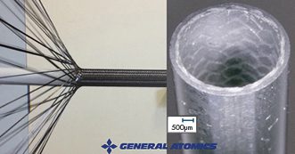
Figure 1. SiGA cladding is a multi-layered composite design composed of SiC fiber in a SiC matrix.

A project is underway to further the development and irradiation testing of a composite silicon carbide matrix as an ATF cladding material. This research is supported through a DOE Funding Opportunity award (DE-FOA-0002308) for the irradiation of a composite silicon-carbide (SiC) ceramic matrix material in an existing U.S. commercial LWR. This work is led by General Atomics – Electromagnetic Systems (GA-EMS) with Structural Integrity Associates (SIA) as a primary subcontractor. For this work, PEGASUS is being adapted to model monolithic and composite SiC manufactured by GA-EMS, SiGA [1], through the incorporation of proprietary material constitutive models. PEGASUS will then be used to provide independent test performance analyses aiding in the design of the irradiation vehicle and predicted material performance. The goal of the testing is to gather irradiation data under prototypic LWR operating conditions and to inform and confirm material performance models for the SiGA-based cladding. A follow-on activity is planned to evaluate the predicted performance compared to data gathered during the post-irradiation examination phase of the project.

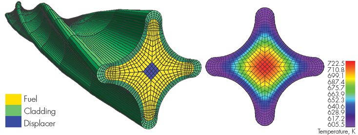
Figure 2. Lightbridge Fuel Design PEGASUS Models

Cruciform Metallic Fuel
An additional fuel concept that has been explored using PEGASUS is a cruciform, extruded metallic fuel design proposed by Lightbridge Corporation [2]. This fuel is characterized by a unique multi-lobed fuel cross-section and features a U-50Zr fuel composition. Recent work has been published on fabrication testing of this proposed fuel design by Pacific Northwest National Laboratory (PNNL) [3]. PEGASUS has been used previously to prototype 2D and 3D geometric models and meshes of Lightbridge fuel and to perform fundamental temperature and stress distributions for this fuel under prototypic LWR conditions. PEGASUS has specific modeling tools designed to facilitate “extruded” 3D fuel designs that automate the meshing of these geometries. More work in this area is planned as a proposal has recently been awarded under the DOE NEUP program (DE-FOA-0002732) funding a collaborative project led by Texas A&M University along with Lightbridge, NuScale, and Structural Integrity Associates, Inc. (SI) for modeling this type of fuel for application in a LWR SMR.


URANIUM METAL ALLOY FUELS FOR SODIUM-COOLED FAST REACTORS
The initial implementation of metallic alloy fuel and stainless-steel cladding material constitutive models for prototypic fast reactor fuel designs in PEGASUS has been completed. Material properties and behavioral models for U-Pu-Zr fuel and HT-9 (high Chromium, martensitic stainless steel) cladding have been added. Ongoing work includes the implementation of a gaseous swelling and fission gas release behavior model for U-Pu-Zr fuel, a Zr-redistribution model, and a fuel-cladding chemical interaction (FCCI) model that includes the effect on cladding wall thinning.

To test the implementation of these models, benchmark tests were prepared that provided comparative data for assessment of the models’ performance. Test cases were chosen from two experimental series irradiated in EBR-II: X430, a 37-pin hexagonal sub-assembly, and X441, a 61-pin bundle. These experiments were designed to test numerous fuel rod design variables and fuel response as a function of fuel alloy composition, smear density, plenum-to-fuel volume ratio, power, and coolant conditions [4]. The general experimental fuel rod design corresponds to the typical driver fuel configuration shown in Figure 3.

Figure 3. Typical EBR-II Mark-III or Mark-IIIA Fuel Element [5]

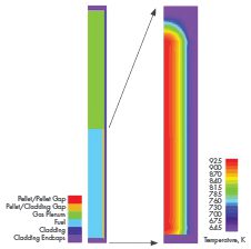
Figure 4. Left: 2D Computational Model of Rod DP2, Right: Temperature Contour Plot of the Fuel Stack Region for Rod DP21 at Peak Power (plenum region removed for detail)

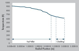
An illustration of the model and selected results from the initial analysis of rod DP21, assembly X441 are shown in the figures above. Figure 4 provides a diagram of the computational model showing the primary components of the model and a plot of the temperature distribution throughout the fueled region of the rod at peak power. Figure 5 provides the radial temperature profile across the fuel rod from the center to the cladding outer surface at peak power near the end of the irradiation period. Temperatures vary from just ~900 K at the pellet center to ~650 K at the cladding surface. The temperature differential is fairly low at ~250 K, as would be expected from a high-conductivity metal fuel rod with a Na-bonded fuel cladding gap. These results are consistent with published experimental observations.

TRISO FUEL MODELING DEVELOPMENT
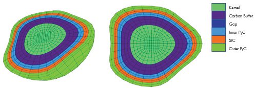
Several advanced fuel material models have been implemented specifically for TRISO fuel in PEGASUS, including thermal and mechanical models for UCO or UO2 kernels, PyC, SiC materials, and a fission gas release model for computing the release of gaseous fission products such as Xe and Kr. In addition to the standard 3D and 2D axisymmetric modeling FEM capabilities in the code, PEGASUS contains several unique tools designed specifically to support TRISO fuel modeling and analysis. These include a “spherical mesh object” tool that can automate the process of generating 2D/3D TRISO spheres, meshing them, and embedding them into a fuel matrix to allow modeling of individual TRISO kernels or fully encapsulated TRISO fuel forms. An example of models generated using the spherical mesh object tool is shown in Figure 6. The spherical mesh object capability is, to our knowledge, unique to PEGASUS and not found in any other fuel performance or general-purpose FEM code. PEGASUS also has a “reshape” function that can automate the process of meshing and modeling deformed TRISO particles to increase user efficiency. Figure 7 illustrates particle meshes that were created using the reshape meshing tool.

These modeling capabilities allow PEGASUS to be used to investigate very detailed mechanical and structural effects in TRISO fuel forms. For example, enabling the detailed analysis of the mechanical interaction between TRISO fuel layers explicitly examining the effects of cracking, debonding, and asphericity within whole or damaged particles.

Figure 5. Radial Temperature Distribution Across the Fuel Rod Model at ~ 486 Days of Irradiation

Planned future development work includes the integration of damage-mechanics modeling and fission product diffusion in the TRISO particle, fuel compact, ad matrix. One failure mode of particular interest that has been identified is cracking of the IPyC layer which propagates through the SiC outer layer. This can create a pathway for enhanced fission product release from the TRISO particle to the surrounding fuel matrix. This failure mechansim appears to occur when the buffer layer remains bonded to the IPyC layer providing the conditions for a synergistic mechanical and chemical failure mechanism that combines cracking, stress concentration, and chemical corrosion (localized Pd-induced corrosion in the SiC [6]. This failure mode is of interest because it can have a strong impact on fuel source term determination for operational TRISO fuel.

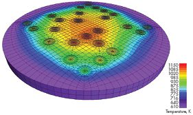
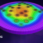
Figure 6. Temperature distribution in a cross-section of a 3D slab of a TRISO compact matrix model with a “sparse”, random kernel distribution under prototypic gas-cooled reactor conditions. (Generated using the “spherical mesh object” tool.)

SUMMARY
PEGASUS is an advanced analysis tool developed for industry applications that can provide a complimentary and independent capability for nuclear fuel performance. Recent development work on PEGASUS has focused on expanding the applicability of the code to the advanced fuel (ATF) and advanced reactor arena. Future development is planned for PEGASUS that will continue along multiple avenues with an emphasis on advanced fuels and specific thermo-mechanical issues within the industry, such as deterministic failure model development. One example of this is the aforementioned Pd-induced failure mechanism identified for TRISO fuel. SI is actively seeking partners within the advanced fuel community to collaborate with on this work and would welcome inquiries and proposals for expanded application of PEGASUS.


Figure 7. Deformed 3D TRISO particle meshes generated using the “reshape” function tool in PEGASUS.

References

  1.   C. P. Deck et al., Overview of General Atomics SiGA™ SiC-SiC Composite Development for Accident Tolerant Fuel, Transactions of the American Nuclear Society, Vol. 120, Minneapolis, Minnesota, June 9–13, 2019.
  2.   J. Malone, A. Totemeier, N. Shapiro, and S.  Vaidyanathan, Lightbridge Corporation’s Advanced Metallic Fuel, Nuclear Technology, Vol 180, Dec. 2012.
  3.  Z. Huber and E. Conte, Casting and Characterization of U-50Zr, PNNL-33873, Pacific Northwest National Laboratory, Richland, Washington 99354, Jan. 2023.
  4.  C. E. Lahm, J. F. Koenig, R. G. Pahl, D. L. Porter, and D. C. Crawford, “Experience with Advanced Driver Fuels in EBR-II,” J. Nucl. Mat. 204 (1993) 119-123.
  5. G. L. Hofman, M. C. Billone, J. F. Koenig, J. M. Kramer, J. D. B. Lambert, L. Leibowitz, Y. Orechwa, D. R. Pedersen, D. L. Porter, H. Tsai, and A. E. Wright. Metallic fuels handbook, Technical Report ANL-NSE-3, Argonne National Laboratory, 2019.
  6. J.D Hunn, C.A. Baldwin, T.J. Gerzak, F.C. Montgomery, R.N. Morris, C.M. Silva, P.A Demkowicz, J.M. Harp, and S.A. Ploger, Detection and Analysis of Particles with Failed SiC in AGR-1 Fuel Compacts, Nuclear Engineering and Design, April 2016.

Get News & Views, Volume 53

News & Views, Volume 49 | Inspection Optimization- Probabilistic Fracture Mechanics

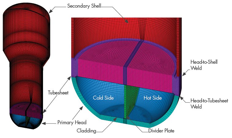
News & Views, Volume 49 | Inspection Optimization: Probabilistic Fracture Mechanics

By:  Scott Chesworth (SI) and Bob Grizzi (EPRI)

News & Views, Volume 49 | Inspection Optimization- Probabilistic Fracture Mechanics

The goal was to determine whether the frequency of current inspection requirements was justified or could be optimized (i.e., increase the interval of certain inspections to devote more attention to higher-value inspections and thereby maximize overall plant safety).

Executive Summary
Welds and similar components in nuclear power plants are subjected to periodic examination under ASME Code, Section XI.  Typically, examinations are performed during every ten-year inspection interval using volumetric examination techniques, or a combination of volumetric and surface examination techniques.  Nuclear plants worldwide have performed numerous such inspections over plant history with few service induced flaws identified.  

SI was selected by the Electric Power Research Institute (EPRI) to review the technical bases for the inspection intervals for select components.  The goal was to determine whether the frequency of current inspection requirements was justified or could be optimized (i.e., increase the interval of certain inspections to devote more attention to higher-value inspections and thereby maximize overall plant safety.)  

An inspection interval review takes into consideration industry operating experience (OE), operating history and previous inspection data.  Many of the components / welds are difficult to access (require scaffolding and removing insulation), require manual techniques of inspection, and are typically in high radiological dose areas.  The inspections can also have significant impact to outage duration.  Reducing the frequency of inspections has the potential for time and cost savings during outages and reduces the radiation exposure to plant personnel.  From the inspection interval review, one utility noted that increasing the inspection interval for steam generator nozzle welds from 10 years to 30 years would save over $600,000 of inspection and supporting activity costs over a 60-year licensed period of operation.  Actual savings for a given plant are situation-dependent, although the potential for significant Operations and Maintenance (O&M) savings exists.

Background

To identify which components and inspection requirements were most suitable for optimization, EPRI performed an initial scoping investigation to collect the following information:

  • The original bases for the examinations, if any;
  • Applicable degradation mechanisms, and the potential to mitigate any potential damage associated with each mechanism;
  • Operating experience, examination data, and examination results, e.g., fleet experience;
  • Previous relief requests submitted to regulators;
  • Industry guidance documents that replace or complement ASME Code requirements;
  • Redundancy of inspections caused by other industry materials initiatives and activities (e.g., Boiling Water Reactor Vessel and Internals Project (BWRVIP), Materials Reliability Program (MRP), etc.); and
  • Existing ASME Code Cases that provide alternatives to existing ASME Code inspection requirements and their bases.

After compilation and review of the information collected, EPRI and their members determined that the inspection requirements for the following components were among the most suitable for optimization:

  • Pressurized water reactor (PWR) steam generator shell and nozzle welds and nozzle inside radius sections;
  • PWR pressurizer shell and nozzle welds; and
  • Boiling water reactor (BWR) heat exchanger shell and nozzle welds and nozzle inside radius sections.

Once the components were identified, EPRI contracted with SI to support development of the technical bases to optimize the related inspections.  These evaluations are documented in the following four EPRI reports, all of which are publicly available for download at www.epri.com:

  • Technical Bases for Inspection Requirements for PWR Steam Generator Feedwater and Main Steam Nozzle-to-Shell Welds and Nozzle Inside Radius Sections, EPRI, Palo Alto, CA: 2019. 3002014590.
  • Technical Bases for Inspection Requirements for PWR Steam Generator Class 1 Nozzle-to-Vessel Welds and Class 2 Vessel Head, Shell, Tubesheet-to-Head, and Tubesheet-to-Shell Welds, EPRI, Palo Alto, CA: 2019. 3002015906.
  • Technical Bases for Inspection Requirements for PWR Pressurizer Head, Shell-to-Head, and Nozzle-to-Vessel Welds, EPRI, Palo Alto, CA: 2019. 3002015905.
  • Technical Bases for Examination Requirements for Class 2 BWR Heat Exchanger Nozzle-to-Shell Welds; Nozzle Inside Radius Sections; and Vessel Head, Shell, and Tubesheet-to-Shell Welds, EPRI, Palo Alto, CA: 2020. 3002018473.

Why It Matters

Recent efforts in the nuclear industry include a focus on reducing the cost of generating electricity to make nuclear more competitive with other sources (natural gas, etc.).  A major component of these efforts is a targeted reduction of plant O&M costs, while ensuring that there is no detrimental impact on plant safety.  Reducing low-value (i.e., low-risk, high-cost) inspections allows plant resources to be devoted to higher value activities (e.g., preventative maintenance).  This is one benefit of employing risk-informed approaches.

The industry (in conjunction with EPRI, SI, and others) has shown a great deal of interest in employing risk-informed approaches where appropriate.  Such efforts include (but are not limited to):

Extremely Low Probability of Rupture (xLPR)

  • ASME Code Case N-702 (alternative requirements for BWR nozzle inner radius and nozzle-to-shell welds)
  • ASME Code Case N-711 (volume of primary interest)
  • ASME Code Case N-716-1 (streamlined risk-informed inservice inspection)
  • ASME Code Case N-752 (risk-informed repair / replacement)
  • ASME Code Case N-770-6 (cold leg piping dissimilar metal butt weld inspection)
  • ASME Code Case N-864 (reactor vessel threads in flange examinations)
  • ASME Code Case N-885 (alternative requirements for interior of reactor vessel, welded core support structures and interior attachments to reactor vessels, and removable core support structures)
  • ASME Code Case N-[xxx] (alternative requirements for pressure-retaining bolting greater than 2 inches in diameter)
  • 10CFR50.69 (risk-informed categorization and treatment of systems, structures, and components)
  • The inspection optimization approach discussed here is congruent with these other approaches, as it uses probabilistic and risk insights to help plants to prioritize inspection and maintenance activities on those components most significant to plant safety.

How It’s Done

In the four EPRI reports cited above, the technical basis for increasing the interval of components inspections included the following steps:
  • Review of previous related projects
  • Review of inspection history and examination effectiveness
  • Survey of components and selection of representative components for analysis
  • Evaluation of potential degradation mechanisms
  • Component stress analysis

Once the above steps were completed, components are subjected to Deterministic and Probabilistic Fracture Mechanics Evaluations.  The DFM and PFM approaches used in the EPRI reports are based on methods used in previous inspection optimization projects, and involved either an increase in examination interval, a reduction in examination scope, or both.  The DFM evaluations were performed using bounding inputs to determine the length of acceptable component operability with a postulated flaw.  The results of the DFM investigation were also to determine the critical stress paths for consideration in the PFM analyses.  The results of the DFM evaluations concluded that all selected components are very flaw tolerant, with the capability of operating with a postulated flaw for more than 80 years.
PFM evaluations were performed to demonstrate the reliability of each selected component assuming various inspection scenarios (e.g., preservice inspection (PSI) only, PSI followed by 10-year in-service inspections (ISI), etc.).  Monte Carlo probabilistic analysis techniques were used to determine the effect of randomized inputs and various inspection scenarios on the probabilities of rupture and leakage for the selected components.  Sensitivity studies are performed to investigate possible variation in the various input parameters to establish the key parameters that most influence the results. 

For each component, probabilities of rupture and leakage were determined for the limiting stress paths in each selected component for a variety of inspection scenarios.  The results of the PFM evaluations demonstrated that the NRC acceptance criteria of 1.0E-6 for both probabilities of rupture and leakage could be maintained for all components for inspection intervals longer than the 10-year intervals defined in Section XI of the ASME Code.  Therefore, the results demonstrate that examinations for the selected components can be extended beyond current the ASME Code-defined interval; in some cases, they can be extended out to the end of the current licensed operating period (at least 30 years for most plants).

Why Structural Integrity

SI is the primary author of the four EPRI Reports cited above (3002014590, 3002015906, 3002015905 and 3002018473).  The inspection optimization projects have provided SI with the opportunity to use its experience in structural reliability to develop a customized PFM software tool named PROMISE (PRobablistic OptiMization of InSpEction), which was used to optimize the inspection schedules for various plant components.  The PROMISE software implemented a probabilistic model of fatigue crack growth using linear elastic fracture mechanics (LEFM) methods, consistent with ASME code, Section XI flaw evaluation procedures.  
The software was developed, verified & validated (V&V), and tested under the provisions of a 10 CFR 50, Appendix B Nuclear Quality Assurance Program.  This tool is based on other, similar previous software codes, and it can be used for similar applications in the nuclear industry where a rigorous technical basis is required to optimize inspection schedules for high-reliability components involving significant outage impact.  In 2020, the NRC staff conducted an audit of PROMISE.  According to the conclusion of the audit report (ML20258A002), the NRC staff gained a better understanding of how PFM principles were implemented in PROMISE and of the V&V on the software.  

In addition to the software audit, SI has supported EPRI and industry in developing responses to NRC requests for additional information (RAIs) for the pilot plant submittals for all four EPRI Reports.  This experience has given SI a great deal of understanding regarding the most efficient and effective way to preemptively address potential NRC concerns in future plant-specific submittals.

How It Would Work For You

For plant owners to use the technical bases established by this work to obtain relief for their plant, they must demonstrate that the representative geometries, materials, and loading conditions used for the selected components bound their plant-specific information.  Based on this analysis, the EPRI Reports provide criteria for each component regarding the component configuration, component dimensions, component materials, applicable transient loadings, and other relevant parameters that must be satisfied on a plant-specific basis.  If all criteria are satisfied on a plant-specific basis for a given component, the results of the investigation can be used for the plant as the technical basis to establish revised inspection schedules for that component.  If any criteria are not satisfied, then plant-specific analysis is required to address any unbounded conditions.  SI can provide support in several areas, including:
Since the technical basis in the EPRI Reports used generic plant configurations, some plant configurations were not included in the analysis.  SI can also support efforts by plants with such configurations to determine whether they are bounded by the criteria of the EPRI Reports.
  • Evaluation of plant-specific parameters against report criteria to determine whether a given plant configuration is bounded
  • Performing plant-specific analysis (e.g., component stress analysis, DFM and PFM, etc.) required to address any unbounded conditions
  • Supporting development of the relief request to proactively address known NRC areas of concern
  • Supporting development of responses to any NRC requests for additional information

Plant Experience To Date

The first plant-specific submittal was made by a U.S. two-unit PWR site in December 2019 based on EPRI Report 3002014590, requesting an inspection alternative to current ASME Code, Section XI examination requirements for steam generator main steam and feedwater nozzle-to-shell weld and inner radii examinations.  The alternative requests an increase in the inspection interval for these items from 10 to 30 years.  The safety evaluation report (SER) for this alternative was received from the NRC in January 2021.

The first plant-specific submittal was made by a U.S. PWR site in December 2019 based on EPRI Report 3002015906, requesting an inspection alternative to current ASME Code, Section XI examination requirements for steam generator Class 1 nozzle-to-vessel welds and Class 2 vessel head, shell, tubesheet-to-head, and tubesheet-to-shell welds.  The alternative requests an increase in the inspection interval for these items from 10 to 30 years.  RAIs for this alternative were received from the NRC in February 2021.  SI supported development of the RAI responses.

The first plant-specific submittal was made by a U.S. two-unit PWR site in December 2019 based on EPRI Report 3002015905, requesting an inspection alternative to current ASME Code, Section XI examination requirements for Pressurizer Head, Shell-to-Head, and Nozzle-to-Vessel Welds.  The alternative requests an increase in the inspection frequency for these items from 10 to 30 years.  RAIs for this alternative were received from the NRC in February 2021.  SI supported development of the RAI responses.

The first plant-specific submittal was made by a U.S. two-unit BWR site in December 2019 based on EPRI Report 3002018473, requesting an inspection alternative to current ASME Code, Section XI examination requirements for Class 2 BWR heat exchanger nozzle-to-shell welds; nozzle inside radius sections; and vessel head, shell, and tubesheet-to-shell welds.  The alternative requests an increase in the inspection interval for these items from 10 years to the end of the plant’s current operating license.  RAIs for this alternative were received from the NRC in February 2021.  SI supported development of the RAI responses.

Conclusion

Inspection optimization offers the opportunity to reallocate plant resources to higher value activities.  In a highly competitive electricity market, the work here has shown opportunity exists to improve O&M costs and maintain safety through effective analysis.  

SI brings to bear the prior experience in developing the methodology with EPRI, proprietary NQA-1 verified software, and decades of industry credibility to support all aspects of the efforts required to institute a program of inspection optimization.  

Get News & Views, Volume 49

News & Views, Volume 49 | Autobook- Nuclear Physics Automation Code

News & Views, Volume 49 | Autobook: Nuclear Physics Automation Code

News & Views, Volume 49 | Autobook- Nuclear Physics Automation CodeBy:  Sasan Etemadi, P.E. and Mark Drucker, P.E.
The AUTOBOOK code reduces human errors, increases efficiency, and streamlines the reload analysis process

AUTOBOOK facilitates plant operation by providing nuclear power plant Reactor Engineers and Reactor Operators with cycle-specific information about the physics characteristics of the reactor core in a core data book document. Structural Integrity has created the AUTOBOOK computer code to automate the creation of this document.

AUTOBOOK is a Quality Assured code developed under a licensee’s software quality assurance (SQA) program. SI provides a full complement of SQA documents, including a Software Requirement Specification (SRS), a Software Design Description (SDD), Verification and Validation (V&V) Plan and Test Report, a User Manual, and Software Installation Instructions (SII).

READ MORE

News & View, Volume 48 | Increase in Reinspection Intervals for BWR Reactor Internals

News & Views, Volume 48 | Increase in Reinspection Intervals for BWR Reactor Internals

By:  Dick Mattson and Minghao QinNews & View, Volume 48 | Increase in Reinspection Intervals for BWR Reactor Internals

A U.S. BWR utility contracted with Structural Integrity (SI) to review their current reinspection guidance documents relative to those contained in the BWRVIP inspection guidelines, the purpose of which was two-fold:

  1. ­Are current reinspection guidelines compliant with industry requirements?
  2. ­Are there components where reinspection intervals could possibly be extended?

READ MORE

News & View, Volume 48 | Fatigue Adjustment Factors for Increased Cyclic Life

News & Views, Volume 48 | Fatigue Adjustment Factors for Increased Cyclic Life

By:  Bill WeitzeNews & View, Volume 48 | Fatigue Adjustment Factors for Increased Cyclic Life

100% of thermal stress was treated as nonlinear gradient stress and linear bending stress was about 12% of the moment stress. Structural Integrity’s (SI’s) review of the stress terms used in piping analysis show that pressure stress does create bending stress in components…

EPRI Report 3002014121 “Development of Fatigue Usage Life and Gradient Factors” has developed fatigue usage adjustment factors that account for: 1) increased cyclic life associated with the growth of potential engineering size fatigue cracks in thicker components (thickness factor, TF; also called life factor, LF), and 2) the presence of through-thickness stress gradients (gradient factor, GF). (TF is used in the issued Code Case.)  These factors are applied to cumulative usage factor, U, in air.

READ MORE

News & View, Volume 48 | Examination Optimization for PWR and BWR Components

News & Views, Volume 48 | Examination Optimization for PWR and BWR Components

By:  Scott Chesworth, Bob Grizzi, and Dilip Dedhia

Optimizing the inspection interval for high-reliability components whose examinations have a significant outage impact.News & View, Volume 48 | Examination Optimization for PWR and BWR Components

Welds and similar components in nuclear power plants are subject to periodic examination under ASME Code, Section XI.  Typically, examinations are performed during every ten-year inspection interval using volumetric examination techniques, or a combination of volumetric and surface examination techniques.  Nuclear plants worldwide have performed numerous such inspections over the plant history with few service induced flaws identified.  Since personnel health and safety, radiation exposure, and overall outage costs associated with these inspections can be significant, Structural Integrity (SI) was contracted by the Electric Power Research Institute (EPRI) to review the technical bases for the inspection intervals for select components.  The goal was to determine whether the frequency of current inspection requirements was justified or could be optimized (i.e., reduced in order to devote more attention to higher-value inspections and thereby maximize overall plant safety).  Special priority was given to components demonstrating an exceptional history of reliability and whose examinations have a significant outage impact.