News and Views, Volume 55 | Replacement of Large Equipment in Nuclear Power Plants
By: Julio Garcia, PhD, PE, Natalie Doulgerakis, PE, SE, Dan Parker, PE and Lachezar Handzhiyski
With many U.S. nuclear plants having extended operation well beyond their original licensed life, it is necessary to replace certain critical process components (e.g., large pumps, turbine rotors, heat exchangers). In many cases, equipment manufacturers are asked to provide larger, heavier equipment to deliver higher output and improve efficiency. Prior to installation, the existing structure must be evaluated for the larger static loads as well as one-time loads applied during movement (transit and rigging). SI has successfully collaborated with owners, design engineers, equipment manufacturers, and installation contractors to ensure safety and minimize disruption during this process.
The U.S. power grid continues to benefit from the extended operation of traditional nuclear power plants, most of which began operation between 40 and 55 years ago. Due to unprecedented market demand, many plant owners are actively pursuing extended operating licenses (subsequent license renewal or SLR), and increased thermal and electrical power output (extended power uprate or EPU). Whether due to normal aging or increased performance demands, many plants are facing the challenge of replacing large pieces of original equipment (e.g., pumps, turbine rotors, heat exchangers) embedded deep within the facility. In many cases, sites are requiring larger and heavier replacement equipment to provide improved efficiency or additional margin.
THE CHALLENGE
Frequently, the initial structural design of these facilities typically did not explicitly account for replacement of certain large equipment (e.g., feedwater heaters, moisture separators, etc.). The removal, hauling, sliding, jacking, and installation of replacement equipment are new tasks that introduce significant operational and structural demands on the building structures as well as challenges to plant staff. High-demand loads may be temporarily imparted to building structures that were optimized during their original design based on original equipment and operations loads with limited strength margins. Re-evaluation of the building structure under the new, larger service loads is required, typically including gravity, seismic, wind, piping, and thermal loads. Particularly challenging and sometimes overlooked are new thermal loads imposed on the gravity load-resisting system of the building. These loads are the result of thermal deformations within the equipment piece itself or within other mechanical attachments, such as piping system that connects to it. Rigorous analyses are performed where there are complex networks of such attachments. Where multiple attachments connect to an equipment piece, it is key to combine the loadings at each attachment location in a conservative, yet realistic manner, to safely demonstrate structural adequacy.
SI has a proven track record of overcoming these challenges by applying rigorous structural analysis, optimizing retrofit strategies, and leveraging multi-disciplinary collaboration to limit disruption and minimize costs.
SI’S ROLE
Structural Integrity (SI) has provided key consulting services to support the replacement of large equipment for SLR and EPU, including moisture separator reheaters (MSRs) and feedwater heat exchangers (FWHs), among others. Working both as task leads, as well as independent reviewers, SI staff have successfully collaborated with owners, design engineers, equipment manufacturers, and installation contractors to safely replace large equipment. SI has provided key consulting related to technical and operational issues, helping to minimize disruption. Additionally, SI has provided a holistic approach that considers the benefits and challenges associated with use of different standards and methodologies to assess and potentially retrofit building structures designed and licensed many decades ago. As a result, SI structural engineers have been praised for providing significant contributions to optimize the process and minimize costs.
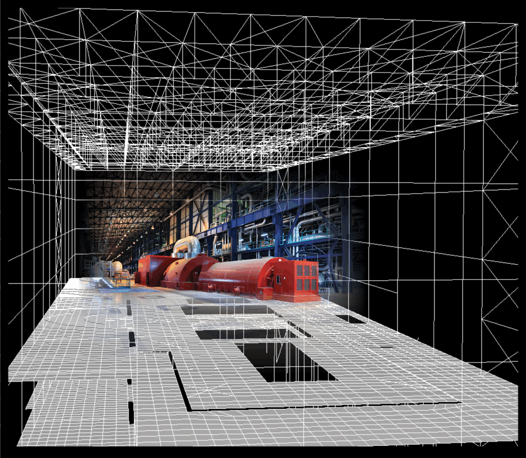
Figure 1. Operating Deck of a turbine building.
KEY SOFTWARE FOR STRUCTURAL ASSESSMENTS
Used for structural analysis and design, GTSTRUDL helps evaluate framing systems and load distribution under gravity, seismic, and equipment-induced forces.
A general-purpose structural analysis tool, SAP2000 assesses floor framing response to new equipment loads, ensuring existing structures can accommodate changes safely.
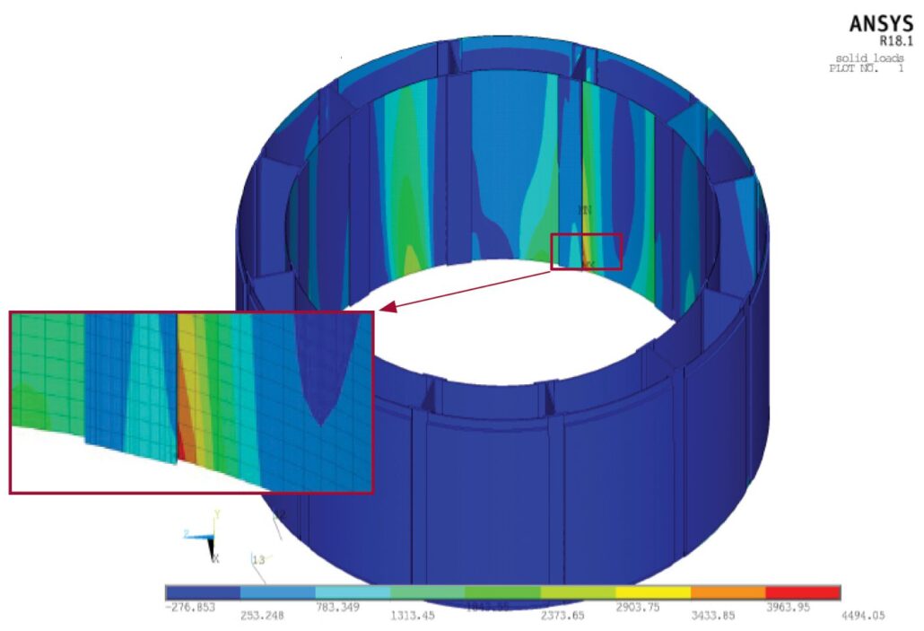
A high-fidelity FEA tool, ABAQUS models localized stress, thermal effects, and nonlinear interactions, providing detailed results in highly-stressed regions to maximize available structural margins.
PIPING ANALYSIS
Used to evaluate thermal, pressure, and mechanical loads applied to large stationary components, piping analysis software ensures system integrity and compliance with applicable codes (e.g., ASME B31.1). SI utilizes PIPESTRESS, AutoPIPE, and CEASAR II for these evaluations, depending on application needs and/or designer preferences.
PROJECT EXAMPLE 1 (1,158 MW 4-Loop PWR)
In support of the planned MSR replacement, SI developed 3-dimensional finite element models of the MSR units and their support frames, as well as the framing at the operating floor of the turbine building.
- Assessed combinations of pipe dead and thermal loads acting at MSR nozzle attachment locations to determine the most critical loading condition on the support frames and floor framing.
- Performed stress analysis of support frames to evaluate structural elements, welds, and bolted connections using ABAQUS.
- Performed structural evaluation of floor framing using SAP2000.
- Calculated framing member and connection capacities using the provisions of AISC 360 and ACI 318.
SI evaluated all structural elements within the MSR load path and confirmed the structure’s adequacy to resist the demands given the design loads provided by the plant staff. The result: SI’s recommendations and selected approach led to no structural retrofits being required of the turbine building, thus ensuring the planned operation was safe to perform while saving the unnecessary expense of reinforcing the structure.
PROJECT EXAMPLE 2 (1,220 MW 4-Loop PWR)
SI acted as the Owner’s engineer and performed an independent review of the MSR replacement project, including a review of the structural analysis of the turbine building under the installation and operation of the new and heavier MSRs, as well as the proposed structural retrofits.
- Independent review of the turbine building analysis methodology and numerical model in GTSTRUDL software.
- Review of loading and requirements data from design basis criteria, calculations, licensing commitments, manufacturer information and transport/hauling information.
- Verification of loading data in GTSTUDL model.
- Assessment of structural member capacity results from GTSTRUDL model.
- Performance of independent calculations for steel-reinforced concrete composite section capacities.
- Provided recommendations on the analysis methodology, loading data and applicable design standards to optimize the strength margins of the existing turbine building.
Through an independent review of the MSR replacement project, SI demonstrated unrealized structural margin, reduced the number of structural retrofits to support the heavier MSR units, and provided recommendations on licensing strategy for the review and approval of the structural modifications supporting the MSRs replacement.
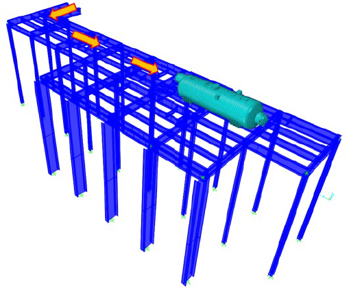
Figure 2. Sliding and Replacement of a Moisture Separator Reheater.


 By: Sasan Etemadi, P.E. and Mark Drucker, P.E.

 On October 28th, the Structural Integrity (SI) Nuclear Fuel Technology Team achieved a major milestone in completing the first Verification & Validation phase in the development of its nuclear fuel performance and behavior code Pegasus©. “This is a significant step by the SI Team” commented Vick Nazareth, SI Fuel Director. “We have been developing Pegasus© since 2017 to incorporate cutting edge computational technology and four decades of fuel behavior modeling and analysis expertise into a software program”. The code addresses a need for deeper fuel integrity insights within the nuclear industry to achieve next level fuel performance and licensing. Dr. Joe Rashid, Scientist and Senior Technology Developer of the code added “this code will analyze fuel behavior through the entire fuel cycle from initial startup to used-fuel storage”.