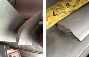
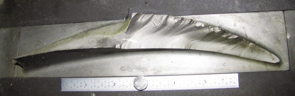
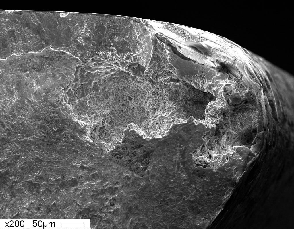
Figure 1. Lower compressor casing after large forward blade liberation, causing a forced outage and catastrophic damage to aft components.
COMPONENT ASSESSMENT AND ANALYSIS
By John Molloy
Structural Integrity (SI) has decades of experience dealing with compressor degradation’s short-term and long-term effects, forced outages, and unforeseen costs regarding Combustion Turbine (CT) compressor hygiene. The inlet package and compressor condition can strongly influence unit performance, efficiency, reliability, risk, and maintenance costs.Controlling what enters the inlet and mitigating the effects of accumulated foreign material can significantly impact O&M activities and costs.
Additionally, in the new paradigm of cyclical operation and potentially longer downtime between operational periods, additional considerations and actions are incumbent upon O&M to prevent irreversible damage to various CT flow path components (compressor, rotor, etc).
In the 51st edition of News & Views, we discussed the CT compressor hygiene regarding component longevity. This follow-up article will dive into the assessments and analyses.
SI is pleased to offer a comprehensive suite of inspections, analyses, and O&M recommendations to help mitigate these debits to reliable, profitable, and safe operation.
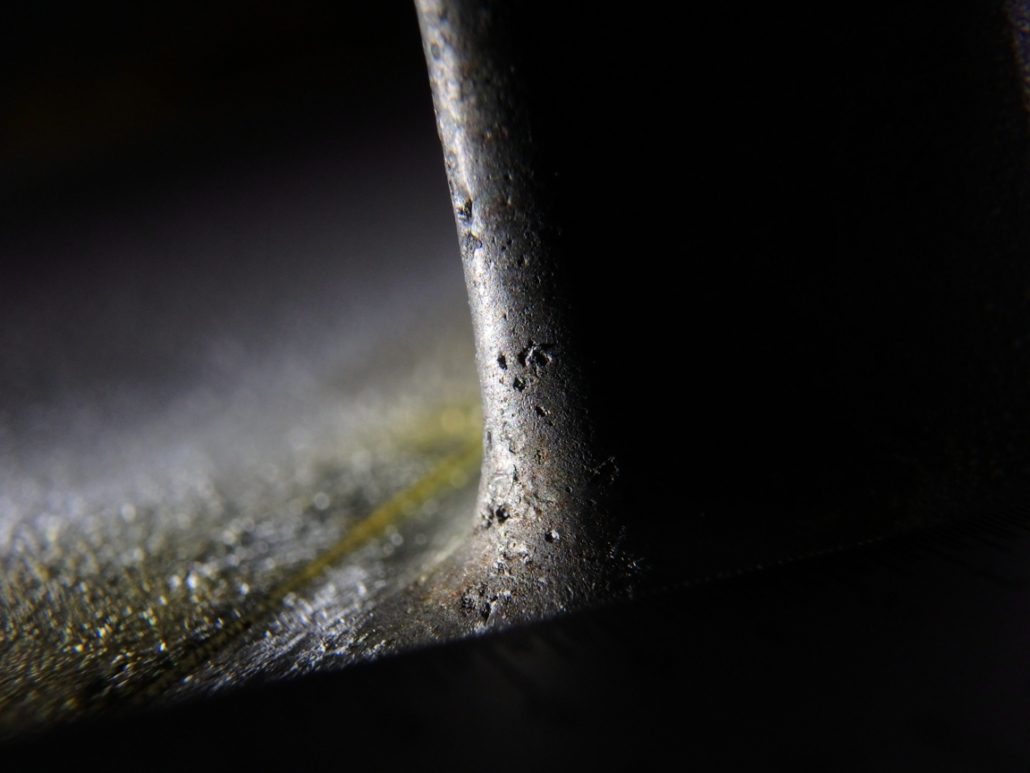
Figure 2. Forward compressor blades with corrosion pitting on the leading edge, platform radius, providing nucleation sites for corrosion fatigue and cracking.
Inlet Package and Forward Compressor Detailed Site Survey
The inlet package and forward compressor site survey is a detailed visual inspection of the inlet filter house/inlet ducting assembly. The inspection allows for documenting potential sources of foreign objects, evidence of sealing issues (floor/wall/roof construction, penetrations, and filter seating), pooling water, corrosion, cracks, cleanliness, and contaminant/debris presence.
The in-depth inspection also examines:
Water injection/misting systems for leaks/contaminant accumulation
Bearing region and compressor leak entry passages for contaminants/debris
Pre-filter deposits/debris collection to determine local environmental loading conditions and corrodents
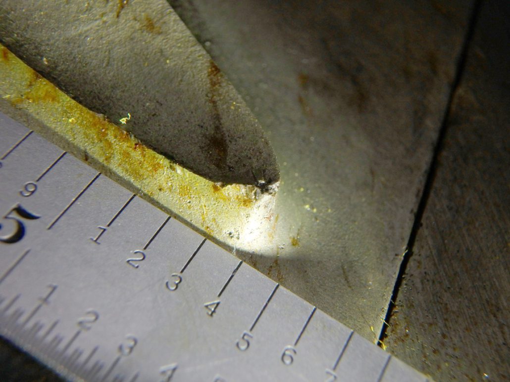
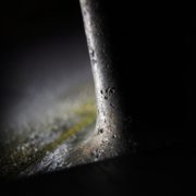
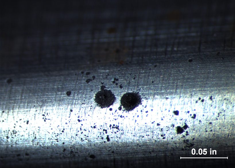
Figure 3. Pitting on compressor blade.
The SI team additionally collects Inlet Guide Vane (IGV) and forward blade, stator vane, rotor, and carrier deposits/residues to establish the presence of contaminants and or corrodents on the compressor, and compares this to the finding in the pre-filters to establish the efficacy of the filtration system. Particular attention is given to the compressor’s lower half, which is usually the area most affected. Photographic documentation of the typical forward compressor (IGV/R0/S0/R1) pitting conditions is completed using a macro lens (Figure 3). In the final step of the survey, the team performs a mold replication on typical pitting and leading edge (LE) erosion.
Data Collection, Analysis, and Review
Figure 4. Leading edge chloride pitting and fracture on a vane.
During the compressor hygiene testing and analyses, there are several areas where data can be collected. This includes ambient and unit flow path humidity trends, ambient and CT inlet temperature/dewpoint, water injection operation, compressor performance, and an annual borescope inspection.
Other data elements potentially collected or reviewed include water wash frequency, duration, and water wash quality checks consisting of pH and chemistry constituents review of the demineralized water source, water wash solution, and drain. In addition, the IGV calibration report, pollution, contaminant producers, and environmental wind condition survey (drift) can be reviewed if the previous findings merit this effort. Finally, the team correlates the observed pitting locations with known risk profiles for blade/vane excitation. Nodal response stresses can be evaluated for a more detailed assessment.
Laboratory Support
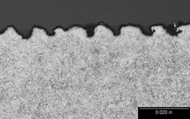
Figure 5. Metallographic cross-section shows leading edge erosion channeling morphology on a forward compressor blade, which facilitates fatigue crack initiation.
SI’s world-class laboratory is leveraged to provide tailored analyses for compressor assessments.
This generally includes:
Inlet prefilter contaminant/debris species analysis
IGV/R0/S0/R1/Wheel/Case surface contamination species analysis
Pitting and/or erosion depth assessment
Blade and vane metallurgical evaluation When parts are available for analysis, the laboratory analyses can provide specific damage mechanisms affecting the components, which allows for better decisions on mitigation strategies. The goal of the assessment and analysis is to close the loop between the on-site unit findings, the operational assessments, to provde the client with best-in-class combustion turbine availability, and performance.
When a unit trips or experiences an event, the site will incur costs associated with the loss in production and regulatory penalties. Based on the severity, the outage scope may include hardware replacement and, if applicable, the purchase of make-up power. These costs can quickly drive the decision to make the return to service the only priority.
With the reduction in staffing at power plants over the past 2 decades, many traditionally routine engineering and maintenance tasks have fallen by the wayside.With limited resources, operations and engineering personnel must focus their time and efforts based on priority.Quite often, keeping a unit online or quickly returning a unit to service will take priority over continuous improvement actions such as investigations and root cause analysis.
When a unit trips or experiences an event, the site will incur costs associated with the loss in production and regulatory penalties. Based on the severity, the outage scope may include hardware replacement and, if applicable, the purchase of make-up power. These costs can quickly drive the decision to make the return to service the only priority. Unfortunately, the review of event operational data, event precursors, and the collecting evidence through the unit disassembly very often falls below the priority of returning to service.Collecting or re-creating evidence after the fact is nearly impossible.This lack of priority often results in a lack of understanding of the root cause of the trip or event.
Within large, complex plants and turbomachinery, trips or minor events are common but are rarely isolated, one-off events. Many trips and events are repetitive in nature and, worse, are early indications of a more serious event to come. While the cost of delays in returning to service may be high, the cost of not solving the root cause may be orders of magnitude higher, particularly if a failure event happens a second time.
Focusing on unit trips, best practices include:
Hold regular, cross-functional trip reviews.
If available, consider holding reviews across similar sites within a parent company.
Utilize knowledge and solutions that may already have been developed.
Trend trip events and frequency over a 1-to-3-year period.
Measure the success of prior projects based on the reduction of occurrences or elimination over a multi-year period.
Trips may be seasonal in nature, and re-occurrence may span timeframes greater than one year.
Review each trip as a near miss and assess potential consequences that may not have occurred this time.
Consider including trip investigation in site or corporate level procedures and celebrate successes.
Focusing on unit events, the cost of an event requiring an outage and hardware replacement, not including make-up power purchase, can very quickly escalate to millions of dollars. Compare that cost to the cost of a dedicated, independent resource for the duration of time required to perform a comprehensive investigation. Also, consider the cost of the investigation versus the cost of reoccurrence or a similar event with more serious consequences. The cost of the resource and investigation will almost always be in the noise of the overall cost. Best practices include:
In nearly all cases, site and outage resources will be dedicated to the speedy rehabilitation of the unit.
Critical evidence is often lost or destroyed, unintentionally, based on the need to return to service quickly.
A dedicated, independent resource provides the best option to ensure that useful evidence is collected.
Assign a dedicated, independent resource to collect and review data and findings.
If a site resource is not available, borrow from a sister site or corporate team, ideally someone with an outside perspective and not necessarily an expert in the field.
Consider an external independent resource such as an industry consultant.
It will likely require a team to complete the overall root cause analysis, however, the likelihood of success will be much greater with facts and details being collected by a dedicated resource.
Initial steps as a dedicated, independent resource:
Ensure a controller and DCS data and alarm logs backup is completed before they time out.
Interview individuals that were on site at the time of the event and or in the days prior.
There is no such thing as too many pictures. It is common to find a critical link or detail in the background of a picture taken for another reason.
Clearly articulate hold points at which the independent resource will require inspections or data collection through the disassembly process.
Collect and preserve samples and evidence.
Where available, utilize other fleet assets to enable a detailed causal analysis with corrective and preventative actions.
Demonstrating a commitment to fleet risk reduction can minimize impacts with regulators and insurers.
Once an event occurs, those limited resources will be fully occupied. Creating a plan at this point is too late.
Discuss including the cost of an investigation into an event insurance claim with site insurers and what their expectations would be to cover the cost.
Maintain a list of resources, internal and external, to call upon as dedicated, independent resources.
Identifying the root cause of an event might be cumbersome, but far less cumbersome than dealing with the same type of event on a recurring basis.
Structural Integrity has team members and laboratory facilities available to support event investigations and to act as independent consultants on an emergent basis.
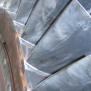
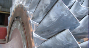
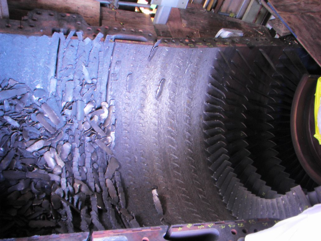
Figure 1. Compressor rotor inlet with fouling deposits
An industrial combustion turbine can ingest over 1000lbs of air per hour of operation.Entrained within the air is a spectrum of mineral, salt, moisture, and VOC, and other compounds that are present in the local atmosphere.Locally high concentrations of potentially corrosive species may also be present due to surrounding industries or even effluent from the power plant itself, such as cooling tower drift, evaporation cooler deposits, or water treatment effluent.
In addition to disrupting the flow path area of the compressor blades and vanes, with a consequential drop in compressor efficiency, these contaminants can also serve as sites for under-deposit corrosion cells that have implications for component life as well as risk for catastrophic failures.Compressor waterwashing with detergents has been utilized with some success by utilities as a method for mitigating the effects of deposit accumulation.Nevertheless, tenacious deposits can accumulate over time.The presence of moisture in the deposit can also result in activation of a corrosion cell that can corrode the typical stainless steels used for blade and vane construction.Higher strength PH stainless steel blades and vanes suffer a larger loss in fatigue endurance limit from pitting, and tend to suffer more airfoil liberations due to cracking initiated at pitting.
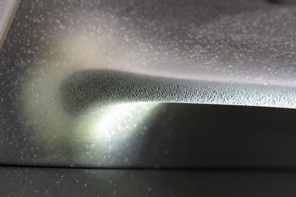
Figure 2. Forward compressor blade with leading edge pitting
On forward compressor blades and vanes, qualified inspectors have also observed combined effects of leading edge erosion and pitting.The erosion is typically the result of on-line water washing.The roughness of the eroded leading edge is now an ideal area for compressor deposits to become deeply embedded.Additionally, it serves as multiple stress concentrations for fatigue crack initiation.
The fall in compressor efficiency, the irreversible damage due to erosion and corrosion pitting, and the risk of catastrophic damage due to fracture initiation at the affected areas, all suggest that O&M staff need to have a strategy to mitigate compressor deposit accumulation, as well as erosion channeling.Additionally, the strategy should also consider the scenario where some deposit accumulation is unavoidable and how to reduce the activation of these deposits.Consideration should also be given to units that have a history of blade failures due to a design limitations that makes them susceptible to corrosion fatigue cracking.In such cases, the unit has a low tolerance to the presence of corrosion pitting for crack initiation.
Figure 3. Fractured forward compressor blade with leading edge pitting at the origin
Typical Sources of Contamination – Land
Local geology and soil can contain large amounts of calcium, iron, magnesium, aluminum potassium, sodium, phosphorus, sulfur, as well as other less common species, including chlorides where the dry land used to be a sea bed.These elements are usually present as a compound, such as a mineral oxide or a salt, but may also be bound with organic material in the soil.Even with reasonably high efficiency filtration that removes 99.7% of the particulates within a given particle size range, the remaining 0.3% contamination multiplied by 1000lbs /hr of influent air results in a high rate of deposit accumulation.Deposits accumulated on airfoil surfaces can then liberate ionic species due to the absorption of moisture, thus creating a corrosion cell.Chlorides due to ubiquitous salts will rapidly corrode (pit) any and all of the stainless steels used in gas turbine compressors, with only partial mitigation by coatings.The only class of compressor materials reasonably immune to chloride or under deposit corrosion is the titanium alloy blades and vanes used in flight turbines and some aeroderivative units.Sulfur containing compounds are also commonly found on the airfoils of compressor blades and vanes, particularly in regions with heavy industry and refining.Sulfur containing compounds can also be extracted and diverted to the hot gas path cooling channels of downstream components, and greatly accelerate hot corrosion in the absence of moisture.
Atmosphere
The local quality of air entering the compressor is somewhat variable, and also dependent on geographic location.Coastal regions have an obvious problem with humid, chloride laden atmosphere.This particular environment is especially vulnerable to chloride pitting.Special inlet ducting and tailored filtration may provide some level of protection.
Figure 4. Fractured forward compressor blade with leading edge erosion at the origin
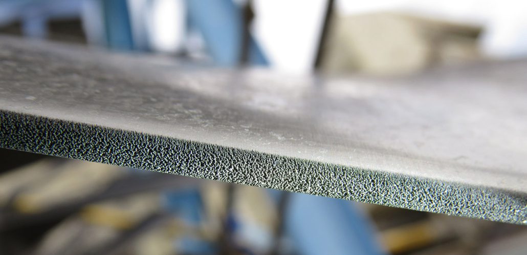
Figure 5. Forward compressor blade with leading edge erosion at platform radius
Local environments due to the proximity of inlets relative to cooling towers and the use of sodium hypochlorite for microbial control of cooling tower water can result in a chloride-laden influent to the unit.In this case the solution may be as simple as using a non-chloride based biocide for microbial control.In some cases the corrodents can come from non-typical activities at the plant, such as excursions of acid vapors from the water treatment facilities (sulfuric acid or hydrochloric acid).
Proximity to local industry, such as steel mills, coal or lignite fired boilers, oil production or refineries can result in a large influent concentration of sulfur bearing compounds.Sulfur bearing compounds, when incorporated into a deposit layer, can accelerate under-deposit corrosion and pitting, as well as aforementioned hot corrosion of downstream turbine components.
Water
Water source used for compressor washing (online and offline), as well as water used for power augmentation (misting, evaporative cooling, etc) should ideally be demineralized quality or better.The use of city water or another source of hard water is generally discouraged.Online water washing with a hard water source can result in increased deposit accumulation at and beyond the phase transition area (stage 2-5 typically) where the water boils to vapor and the dissolved minerals will deposit onto the blade /vane surfaces.Power augmentation by closed loop chiller systems also affords the opportunity for contamination due to leaks in the chilled fluid.These fluids can have variable water quality as well as chemicals added to the chiller loop.Non volatile constituents of the chilled water may leave deposits in a similar fashion as hard water.Evaporative cooling with hard water will result in mineral shedding that can accumulate downstream.As mentioned, on-line water washing will often cause leading edge erosion channeling, and more severely if the droplet size is not controlled, or leaking occurs during operation.
Historical Contaminants Observed in Compressor Deposits
Over the course of many years, we have been privileged to sample the deposits laden on blades and vanes from gas turbine units in many parts of the world.A pattern of contaminants (the usual suspects) has been observed, with some exceptions.The deposits observed are biased largely by one of the dominating contributors:Coastal conditions, land conditions, or local plant and industrial environment (neighboring industry or locally produced effluent).
Figure 6. Forward compressor blade with leading edge erosion at airfoil mid span
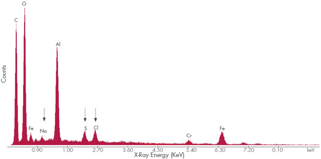
Energy Dispersive Spectroscopy (EDS) provides qualitative elemental analysis of materials under scanning electron microscopy (SEM) examination based on the characteristic energies of x-rays produced by the electron beam striking a deposit sample.The relative concentrations of the identified elements are determined using semiquantitative, standardless quantification (SQ) software.This information can be used to tailor the filtration system and media, as well as the detergents used in compressor washing.It may also provide leverage for high level dialog with the local regulators and emitting sources.
Conclusions
The corrosion pitting on the compressor blades and vanes is almost always the result of under-deposit corrosion aggravated by the presence of corrosive species in the deposit.The corrosive species are often sulfur and chlorine-containing compounds, but pitting can also occur from simply the presence of oxygen under the deposit (oxygen pitting).The pitting is proof of corrosive deposits, and trace amounts of corrosive species identified by EDS at the bottom interface of the pits identifies the active corrodents so that treatment can be fine-tuned for that species.
The source of the corrodents can be local to the plant (cooling tower drift), in the soil, from the atmosphere (coastal chlorides) or from local industry (burning lignite or low grade coal, and / or oil and gas production).In some cases the corrodents can come from non-typical activities at the plant, such as the use of sodium hypochlorite (bleach) for biological control, or excursions of acid vapors from the water treatment facilities (sulfuric acid or hydrochloric acid).Plant operations can identify, address and mitigate the local sources.
Starts-based units, or peakers, also have life-limiting pitting that is difficult to understand without considering the effect of off-line corrosion.For units operating in cycling duty, a substantial amount of time is spent in idle mode.During idle periods, the unit is normally stationary or on turning gear for some daily period.After the rotor is ambiently cooled during the nightly lows, the rotor will retain much of the lower temperature relative to the increasing ambient temperature and humidity during the day.As a result the rotor will sweat like cold drink on a warm day, and the deposits on the blades and vanes will be similarly affected.This is a common mechanism for deposit activation and corrosion that seems to be aggravated by the new paradigm of unit cycling.These are the periods where corrosive deposits combined with moisture will create conditions ideal for pitting, particularly if the airfoil deposits contain a substantial concentration of sulfur and chlorine-containing compounds.
Mitigation
Units may be waterwashed online each day when operated and the ambient temperature is greater than about 50°F.Offline water washing may be performed prior to performance testing or to restore lost capacity.In both cases the water washing is performed to provide performance benefits and also to prevent the accumulation of corrosive deposits.However, performing an online waterwash prior to operation does not remove the deposits accumulated during the subsequent operation cycle, nor does it remove much deposit beyond the second stage due to phase transition from liquid to vapor.Moreover, if the subsequent operation cycle is followed by a long idle period in humid weather, the deposits can absorb the ambient moisture and activate the corrodents.Off-line washes must be performed with demineralized water and a cleaning solution tailored to the deposits.Proper rinses with conductivity measurements taken at the drain ports are advised.Offline water washing is much more effective at removing compressor deposit accumulation, but proper drying is necessary to prevent pitting under remaining, tenacious deposits.
Figure 7. EDS Spectrum of compressor fouling deposits. Chlorides, sulfur deposits, and sodium deposits can be corrosive to stainless steels.
Another aspect of the operation that can affect the compressor deposits and moisture is proper sealing of the inlet filter house.All seams should be sealed with a weatherproof material and the fitment surfaces should be in good condition.Water leaks from the roof or any other area that causes standing water should be addressed.Additionally, corroded surfaces should be prepped and painted to stop the corrosion.Any bolts, nuts, and screws should be inspected for significant corrosion and potential loss of material that can become foreign object damage.
From a mitigation standpoint, two aspects must be addressed to reduce the susceptibility to pitting.First, the accumulation of deposits must be reduced.This may be achieved by higher efficiency filtration media (such as HEPA and hydrophobic Gore® Filters) and more aggressive offline water washing with a cleaning solution tailored to the deposits.Second, the presence of unwanted water must be reduced.Waterwashing should be followed by operation to ensure all moisture is evaporated.Water repelling filtration (such as Gore® filtration media) may reduce some of the water ingestion during wet weather, and may also prevent some of the influent from cooling tower drift (Gore® filtration medial is quite expensive, so a cost-benefit analysis may be require do to justify the additional expense).Long idle or layup periods should be combined with closure of the bellmouth and with a dry air source (heater or dehumidifier) to ensure that corrosive deposits are not activated.Mist eliminators and auto-close stack dampers are also beneficial, and should have some effect on reducing the ingress of moisture into the combustion turbine unit.
A detailed unit inspection may be advised, during which time deposit samples can be collected from the pre-filters, conical filters, and forward compressor blades / vanes / IGVs for corrosive species survey, as well as establishing the efficacy of the current filtration system.At this time, the severity of any pitting can also be documented.Additionally, mold replication can be performed on the LE of the forward compressor blades to gauge the severity of erosion channeling, which is often governed by OEM technical letters or service bulletins. A survey of the inlet filter house is also advised, where potential points of uncontrolled ingress can be identified.Additionally, the structure can be mapped for corrosion, cracked or damaged structures, and potential fastener liberation.
OEMs recommend periodic inspection of pinned finger turbine blade attachments for detection of service-induced damage as part of ongoing rotor maintenance activity.
This article provides an example where ultrasonic inspection detected cracking in several pins of finger attachments and outlines an engineering assessment to support continued operation and identify a re-inspection interval.This approach can be applied to other pinned finger blade attachments to determine suitability for service.
Three factors typically drive inspection intervals of generator rotors:
a timeframe recommended by the insurance carrier or OEM
an engineering evaluation that supports a different inspection interval due to service operation events or existing rotor damage
industry best practices
Drivers from the OEM include issues defined in service bulletins or technical information letters that pertain to the entire fleet or some subset of the population. Intervals based on engineering evaluations can be derived from an identified damage mechanism with the rotor or with a critical component. An engineering evaluation can also provide for extended inspection intervals in situations where the generator has no inherent material issues, has a clean inspection record, and sees limited operational stress such as in a base-load unit.
We may request cookies to be set on your device. We use cookies to let us know when you visit our websites, how you interact with us, to enrich your user experience, and to customize your relationship with our website.
Click on the different category headings to find out more. You can also change some of your preferences. Note that blocking some types of cookies may impact your experience on our websites and the services we are able to offer.
Essential Website Cookies
These cookies are strictly necessary to provide you with services available through our website and to use some of its features.
Because these cookies are strictly necessary to deliver the website, refusing them will have impact how our site functions. You always can block or delete cookies by changing your browser settings and force blocking all cookies on this website. But this will always prompt you to accept/refuse cookies when revisiting our site.
We fully respect if you want to refuse cookies but to avoid asking you again and again kindly allow us to store a cookie for that. You are free to opt out any time or opt in for other cookies to get a better experience. If you refuse cookies we will remove all set cookies in our domain.
We provide you with a list of stored cookies on your computer in our domain so you can check what we stored. Due to security reasons we are not able to show or modify cookies from other domains. You can check these in your browser security settings.
Google Analytics Cookies
These cookies collect information that is used either in aggregate form to help us understand how our website is being used or how effective our marketing campaigns are, or to help us customize our website and application for you in order to enhance your experience.
If you do not want that we track your visit to our site you can disable tracking in your browser here:
Other external services
We also use different external services like Google Webfonts, Google Maps, and external Video providers. Since these providers may collect personal data like your IP address we allow you to block them here. Please be aware that this might heavily reduce the functionality and appearance of our site. Changes will take effect once you reload the page.
Google Webfont Settings:
Google Map Settings:
Google reCaptcha Settings:
Vimeo and Youtube video embeds:
Other cookies
The following cookies are also needed - You can choose if you want to allow them:
Privacy Policy
You can read about our cookies and privacy settings in detail on our Privacy Policy Page.


 With the reduction in staffing at power plants over the past 2 decades, many traditionally routine engineering and