News & Views, Volume 53 | Encoded Phased Array Ultrasonic Examination Services for Cast Austenitic Stainless Steel (CASS) Piping Welds
IN PRESSURIZED WATER REACTOR (PWR) COOLANT SYSTEMS
By: John Hayden and Jason Van Velsor
The CASS piping welds present in many PWR plants provide numerous and complicated challenges to their effective ultrasonic examinations. To this point, a viable ultrasonic examination solution for the inspection of these piping components, as required by ASME Code Section IX, had previously not been available. By leveraging our technical expertise in materials, technology development, and advanced NDE deployment, Structural Integrity Associates, Inc (SI) has developed a new system that will provide a meaningful solution for the examination of CASS piping components. The result of this program will be the first commercial offering for the volumetric examination of CASS components in the nuclear industry.
BACKGROUND INFORMATION
ASME Section XI Class 1 RCS piping system welds fabricated using CASS materials pose serious and well-understood challenges to their effective ultrasonic examination. For decades, utilities and regulators have struggled with the administrative and financial burdens of Relief Requests, which were, and still are, based on the inability to perform meaningful volumetric examinations of welds in CASS components.
Many years of futility and frustration may have fostered the belief that technology allowing effective and meaningful examination of CASS materials would never be achievable. This is no longer the case.
The failure mechanism for CASS material occurs through the loss of fracture toughness due to thermal aging embrittlement. The susceptibility of CASS material to thermal aging embrittlement is strongly affected by several factors, primary of which are system operating time and temperature, the casting method used during component manufacture, and molybdenum and ferrite content. In addition to the existing ASME Section XI requirements for the examination of welds in CASS materials, the susceptibility to thermal aging embrittlement drives the requirement for additional examinations (including ultrasonic examinations) as directed by several NRC-published NUREGs required for plant license renewal. The existence of a viable, effective examination capability for CASS materials plays a very important part in both currently required Inservice Inspections (ISI) and plant license renewal.
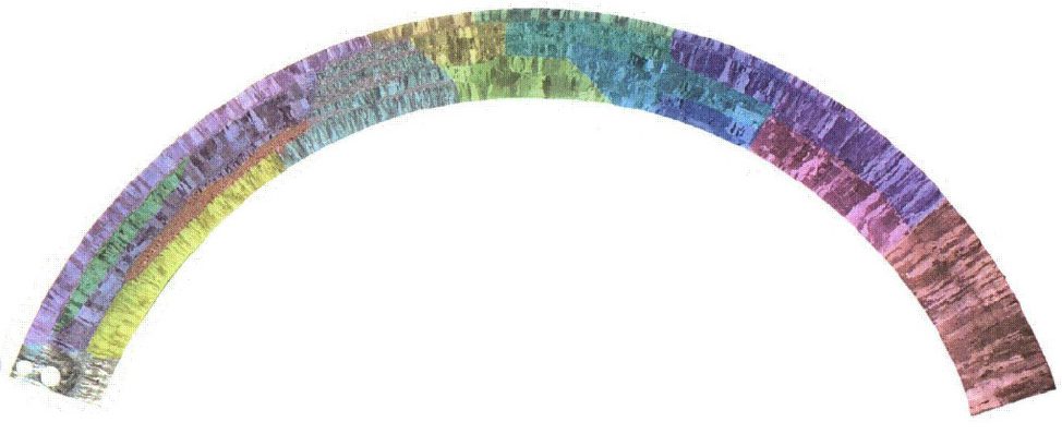
Figure 1. An example of the widely-varying microstructure of a centrifugally cast piping segment. False-color imaging is used to aid visualizing grain variations. (Image from NUREG/CR-6933 PNNL-16292)
CASS MATERIAL PROPERTIES AND EFFECT ON ULTRASONIC EXAMINATION
Metallurgical studies have revealed that the microstructure of CASS piping can vary drastically in the radial (through-wall) direction, as well as around the circumference and along the length of any given piping segment. Large and small equiaxed, columnar and mixed (combinations of equiaxed and columnar grains), and banding (layers of substantially different grain structures) are commonly observed in CASS piping materials. None of these conditions favor the performance of effective ultrasonic examinations.
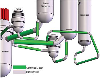
Figure 2. PWR RCS Major Components
The very large and widely varying types (equiaxed, columnar, and randomly mixed), sizes and orientations of the anisotropic grains in CASS material are very problematic. Anisotropic is defined as an object or substance having a physical property that has a different value when measured in different directions. Such physical properties strongly affect the propagation of ultrasound in CASS material by causing severe attenuation (loss of energy through beam scattering and absorption), beam redirection, and unpredictable changes in ultrasonic wave velocity. These factors are responsible for the inability of ultrasonic examination to completely and reliably interrogate the Code-required volume (inner 1/3 Tnom) of welds in CASS piping material. Interestingly, CASS materials less than 1.6” Tnom (Pressurizer Surge Piping) can be effectively examined, while CASS materials over 2.00” (Main RCS Coolant Loop Piping) are less effectively examined. Consequently, an ASME Section XI, Appendix VIII qualification program for CASS piping components has not been established and remains in the course of preparation. Nonetheless, ASME Section XI requirements to conduct inservice examinations of RCS piping welds fabricated from CASS components remain fully in force.
ASME CODE ACTIONS AFFECTING CASS PIPING EXAMINATIONS
ASME Section XI Code Case N-824, “Ultrasonic Examination of Cast Austenitic Piping Welds From the Outside Surface,” was approved by ASME in October 2012 and by the NRC in October 2019. This Code Case provides the first approved direction for the ultrasonic examination of welds joining CASS piping components. The ASME B&PV Code, Section XI, 2015 Edition, incorporates Code Case N 824 into Mandatory Appendix III in the form of Mandatory Supplement 2. To date, these two ASME Section XI Code documents remain the sole sources approved by ASME and NRC that provide specific direction for the examination of CASS RCS piping system welds and, therefore, form the foundation of SI’s approach for the development of our CASS ultrasonic examination solution.
SI’S CASS PROGRAM DESCRIPTION
SI is developing the industry’s most well-conceived and capable ultrasonic system for the examination of welds in CASS piping components. To accomplish this objective, SI has drawn upon our internal knowledge and experience, supplemented by a careful study of numerous authoritative bodies of knowledge relating to the examination of CASS components. The development of the SI examination system has been guided by both SI’s industry-leading 17 years of experience conducting phased array examinations in nuclear power plants and the knowledge acquired through the careful study of the topical information contained within industry-recognized publications. These published results of extensive industry research provided both guidance for the selection of phased array system components and CASS-specific material insights that strengthen the technical content of our Appendix III-based procedure.
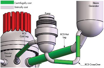
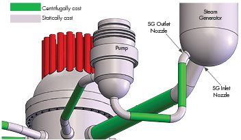
Figure 3. RCS Coolant Pump and Crossover Piping
CASS PROGRAM ELEMENTS
SI believes that the procedure, equipment and personnel featured in this program will be equivalent or superior to those that will form the industry-consensus approach for CASS ultrasonic examinations needed to successfully achieve Appendix VIII, (future) Supplement 9, “Qualification Requirements for Cast Austenitic Piping Welds.”
Ultrasonic Procedure – SI has crafted an ultrasonic examination procedure framework that is fully compliant with ASME Section XI, Mandatory Appendix III, Supplement 2, along with referenced Section XI Appendices as modified by the applicable regulatory documents.
Ultrasonic Equipment – SI has acquired and assembled the ultrasonic system components required by Code Case N-824 and Appendix III, Supplement 2, which includes the following:
- Ultrasonic instrumentation capable of functioning over the entire expected range of examination frequencies. The standard examination frequency range extends from low-frequency, 500 KHz operation for RCS main loop piping welds through 1.0 MHz for pressurizer surge piping.
SI has designed and acquired additional phased array transducers that meet the physical requirements of frequency, wave mode, and aperture size and are capable of generating the prescribed examination angles with the required focal properties. SI has designed and fabricated an assortment of wedge assemblies that will be mated with our phased array probes to provide effective sound field coupling to the CASS components being examined. SI’s wedge designs consider the CASS pipe outside diameter and thickness dimensions and employ natural wedge-to-material refraction to assure optimal energy transmission and sound field focusing.
SI also possesses several data encoding options that are necessary to acquire ultrasonic data over the expected range of component access and surface conditions. The encoding options will include:
- Fully-automated scanning system, capable of driving the relatively large and heavy 500KHz phased array probes
- The SI-developed Latitude manually-driven encoding system, which has been deployed during PDI-qualified dissimilar metal DM weld examinations in nuclear power plants
Figure 4. Steam Generator Details
Examination Personnel – SI’s ultrasonic examination personnel are thoroughly trained and experienced in all elements of encoded ultrasonic data acquisition and analysis in nuclear plants. SI’s examiners have a minimum of 10 years of experience and hold multiple PDI qualifications in manual and encoded techniques. SI recognizes the challenges that exist with the examination of CASS piping welds and has developed a comprehensive program of specialized, mandatory training for personnel involved with CASS examinations. This training includes descriptions of coarse grain structures, their effect on the ultrasonic beam, and the expected ultrasonic response characteristics of metallurgical and flaw reflectors, as well as the evaluation of CASS component surface conditions.
ULTRASONIC TECHNQUE VALIDATION
Although not required by the ASME Code, SI has arranged for access to CASS piping system specimens from reputable sources to validate the efficiency of our data acquisition process and the performance of our ultrasonic examination techniques. The specimens represent various pipe sizes and wall thicknesses and contain flaws of known location and size to permit the validation and optimization of SI’s data acquisition and analysis processes. SI will thoroughly analyze, document, and publish the results of our system performance during the examination of the subject CASS specimens.
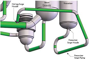
Figure 5. Pressurizer and Surge Line Details
CASS PIPING SYSTEM APPLICATIONS
Typical CASS Piping Weld Locations in PWR Reactor Coolant Systems
The following graphic illustrates the location and extent of CASS materials in the RCS of many PWR plants.
RCS Main Loop Piping Welds: This portion of the RCS contains large diameter butt welds that join centrifugally cast stainless steel (CCSS) piping segments to statically cast stainless steel (SCSS) elbows and reactor coolant pump (RCP) casings. RCS main loop piping includes the following subassemblies:
- Hot leg piping from the Reactor Vessel Outlet to the SG Inlet
- Cross-over piping from the SG Outlet to the RCP Inlet
- Cold leg piping from the RCP Outlet to the RPV Inlet
Steam Generator Inlet / Outlet Nozzle DM Welds: These terminal end DM butt welds are present in PWR plants, both with and without safe ends between the SCSS elbows and the ferritic steel nozzle forgings.
Pressurizer Surge Piping Welds: This portion of the RCS contains a series of butt welds fabricated using CCSS piping segments to SCSS elbows between the Pressurizer Surge nozzle end and the Hot Leg Surge nozzle.
SUMMARY
The CASS piping welds present in many PWR plants provide numerous and complicated challenges to their effective ultrasonic examinations. SI’s new CASS ultrasonic examination system will provide a new and meaningful solution.
PROJECT TIMELINE
SI is working to complete the development, integration and capability demonstrations of the CASS ultrasonic examination system described in this document for limited (emergent) fall 2023 and scheduled deployments beginning in spring 2024.

