News and Views, Volume 55 | Nonintrusive and Robotic Solutions for Tank Asset Management
By: Jason Van Velsor
Nuclear plant aging management programs require periodic inspections of liquid storage tanks. Traditional inspection methods can be disruptive, requiring tanks to be drained to provide personnel access. SI has developed innovative solutions, including screening techniques that can identify degradation from the tank exterior, and submersible robotics that perform comprehensive NDE without draining. Although initially developed for nuclear applications, these technologies can be employed at conventional power generation, petrochemical, and municipal utility facilities.
Nuclear Industry Guidelines
The nuclear industry established guidelines for integrity management of underground piping and tanks in the early 2000s with the publication of NEI 09-14. More recently, additional constraints have been imposed for plants pursuing life extension, especially for sites applying for subsequent license renewal (SLR) to extend permitted operation from 60 to 80 years. These new requirements for outdoor and large atmospheric tanks are conveyed in the form of specific guidelines for aging management programs (AMPs) within NUREG-1801, Revision 2 and NUREG-2191, Revision 1.
 The guidelines within the NUREG documents apply to:
- All metallic outdoor tanks constructed on soil or concrete.
- Indoor metallic storage tanks with capacities greater than 100,000 gallons, designed for internal pressures approximating atmospheric conditions, and exposed internally to water.
- Other indoor metallic tanks that sit on, or are embedded in, concrete, where plant-specific operating experience reveals that the tank bottom (or sides for embedded tanks) to concrete interface is periodically exposed to moisture.
- For utilities with tanks meeting the above criteria, license renewal commitments generally necessitate performing examinations under one of the following three categories:
- Inspection of the bottom 20% of walls for wall loss and cracking.
- Inspection of the outer two feet of the floor plates for pitting/cracking.
- 100% inspection of the bottom floor plates.
Conducting floor inspections using traditional approaches that require draining and personnel entrance into the tank can be undesirable, given the potential impact on operations, as well as the possibility for certain tanks to contain radiological content. For this reason, many utilities have begun pursuing alternative solutions to safely and accurately perform tank inspections.
Traditional Approaches
Historically, utilities have emptied and entered tanks to conduct manual floor inspections. The scope of these examinations can range anywhere from visual to full volumetric inspection of the tank floor using electromagnetic or ultrasonic techniques. More recently, utilities have attempted to utilize robotically deployed examination methods to avoid emptying and entering tanks. Obtaining large-area NDE coverage of tank floors with robotic methods has usually fallen into one of two categories:
- Relatively simple robotic systems that deploy traditional NDE sensors for localized measurements, which may take an impractical amount of time to reliably obtain the required coverage, or…
- Relatively complex robotic systems that deploy a large quantity of traditional NDE sensors to obtain the required coverage more quickly, but that are large, complex, and often expensive to deploy.
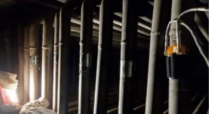
 Deploying any robotics in tanks is a challenging endeavor, with many practical factors that affect the ease and success of implementation. Several of these factors include:
- Accessibility – there are limited access points to the inside of a tank; they are often on top of the tank, and just large enough for a person to fit through.
- Visibility – maneuvering within a liquid-filled tank often relies on optical methods, which are impaired or even ineffective in murky or opaque liquid.
- Navigation – with poor visibility, continuously tracking the position of a robot within a tank (and hence, the location of acquired data) can be unreliable.
- Cleanliness – sediment present in the tank can impair data acquisition and cause additional visibility issues if agitated by the robot.
- Geometry – getting complete coverage at the tank edges and around internal features can be challenging or impossible given the size and limited maneuverability of some robotic systems.
- Tank Size / Inspection Time – for large tanks, obtaining complete coverage of all in-scope surfaces may require extended scanning time, which can impact operations and delay return to service.
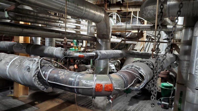
- Liners/Coatings – tanks that have been lined with thick coatings such as fiberglass or carbon wrap can render traditional NDE methods useless.
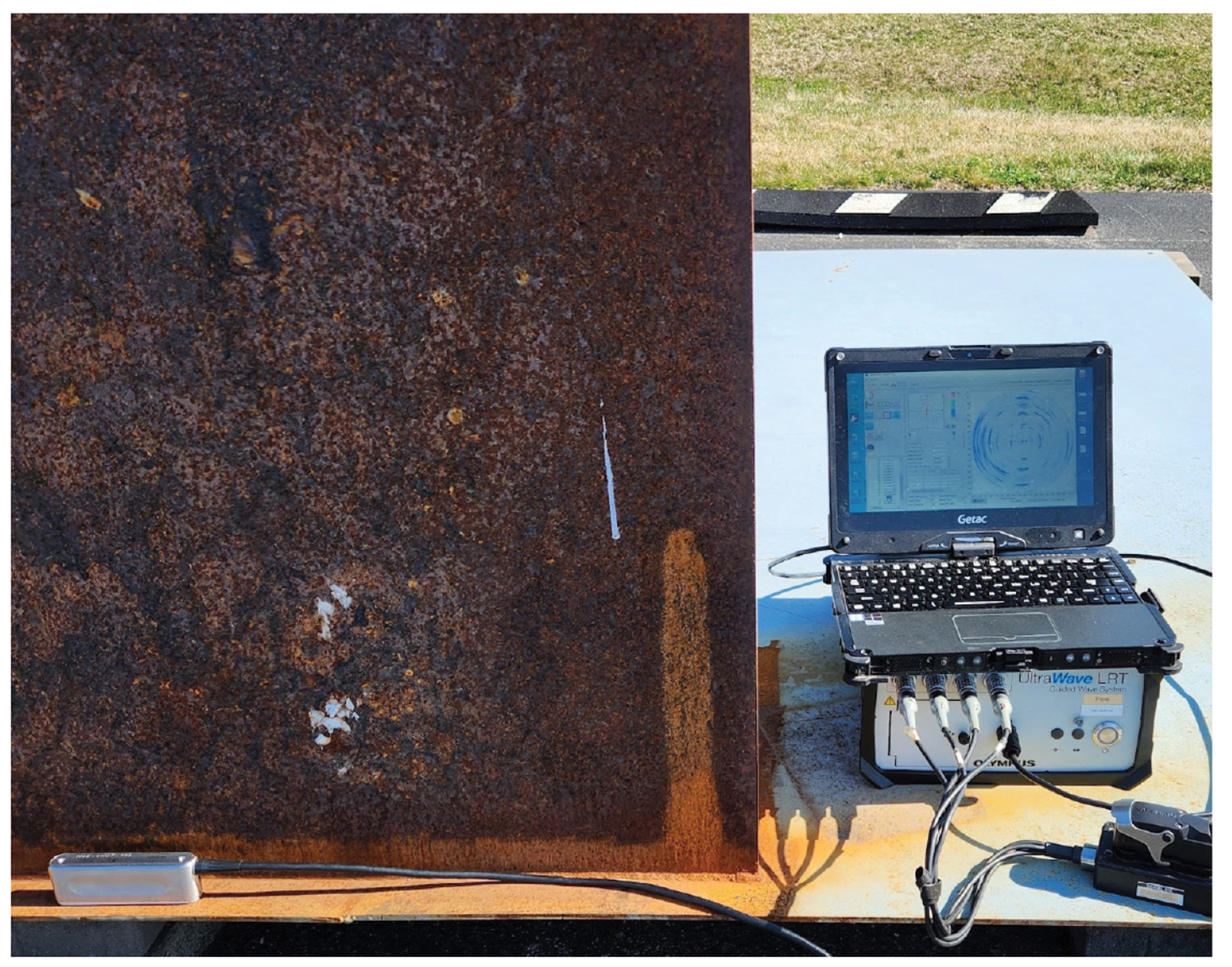
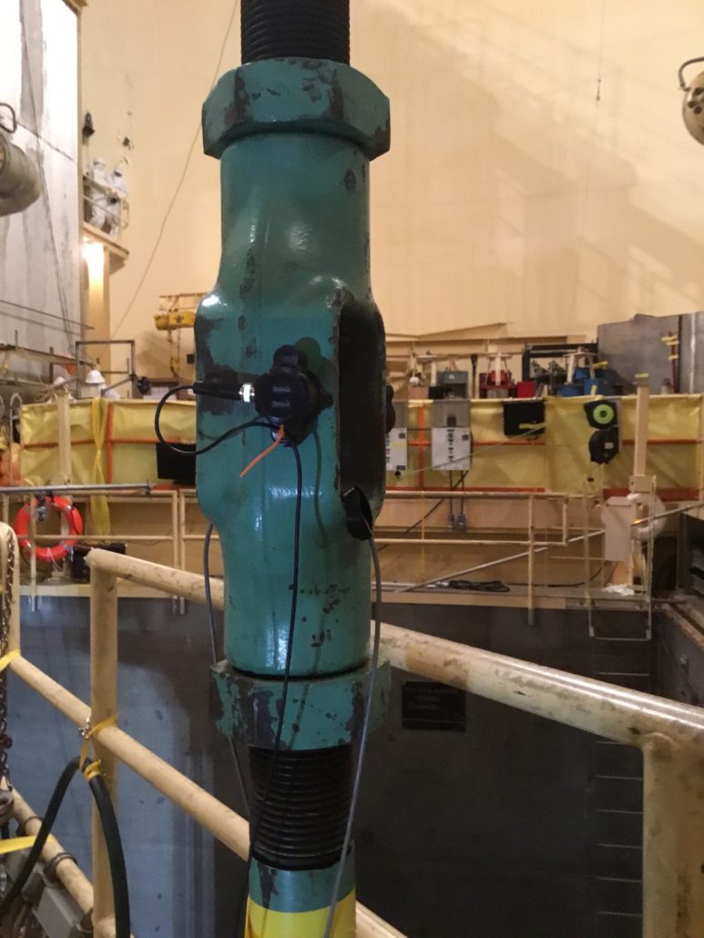
Figure 1. GWPA from Tank Chime
SI’s Approach
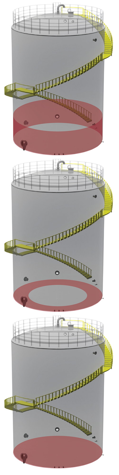
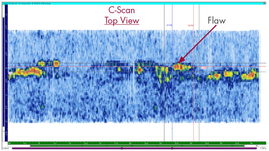
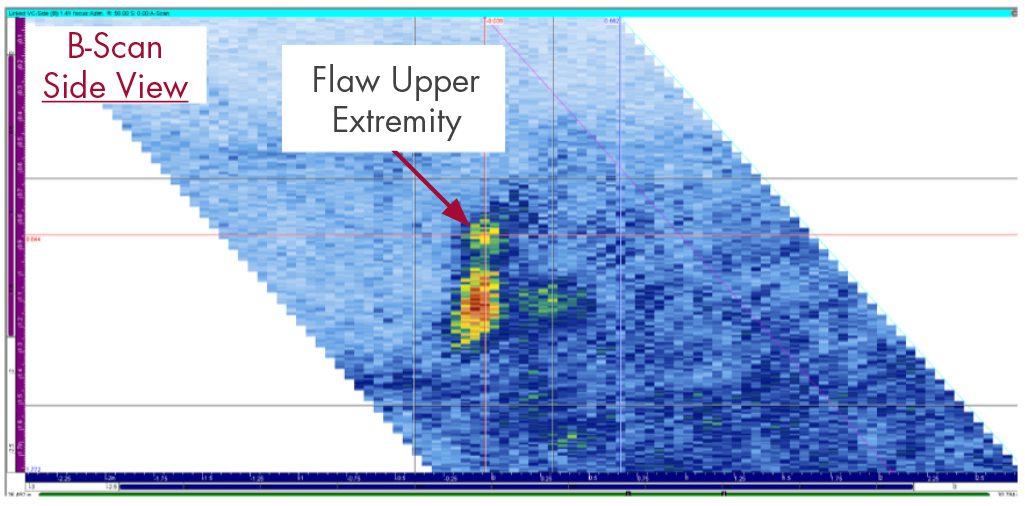
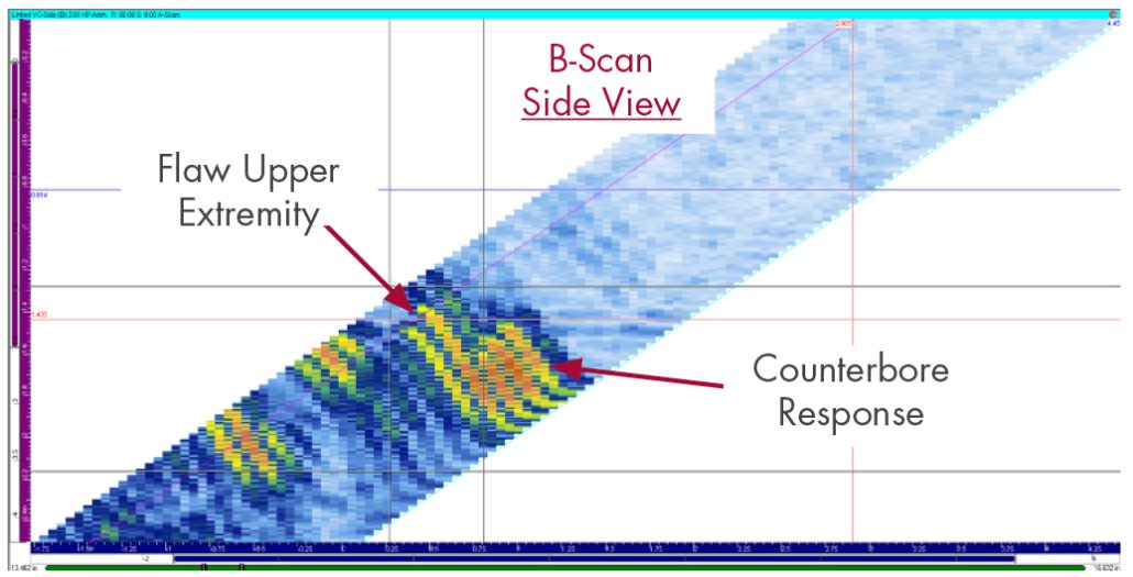
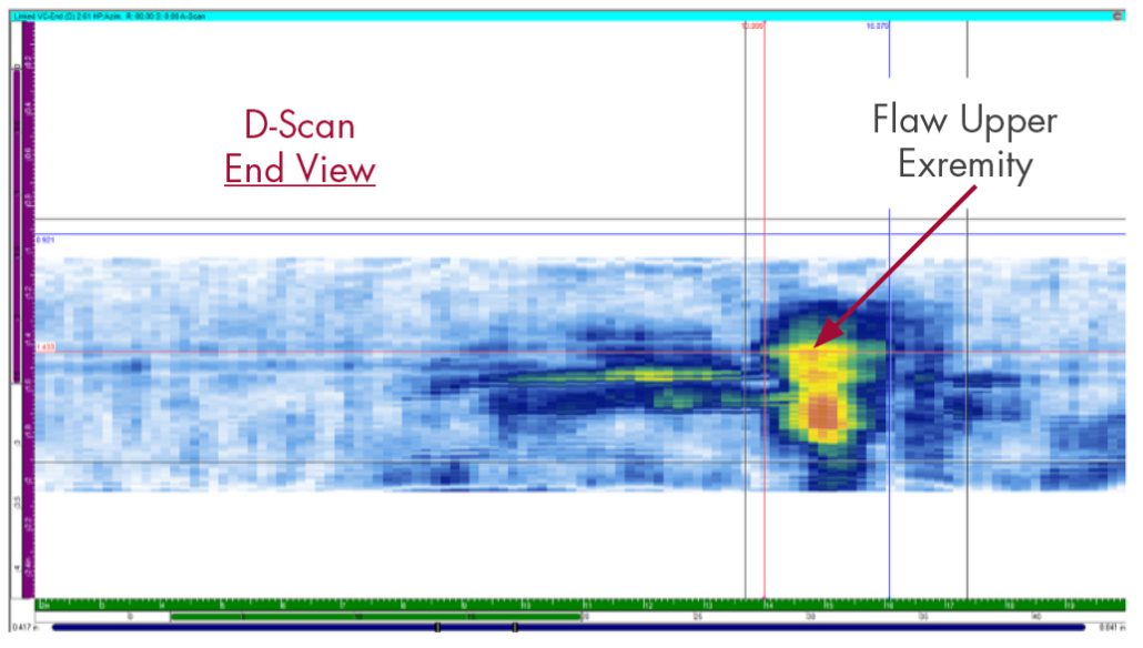
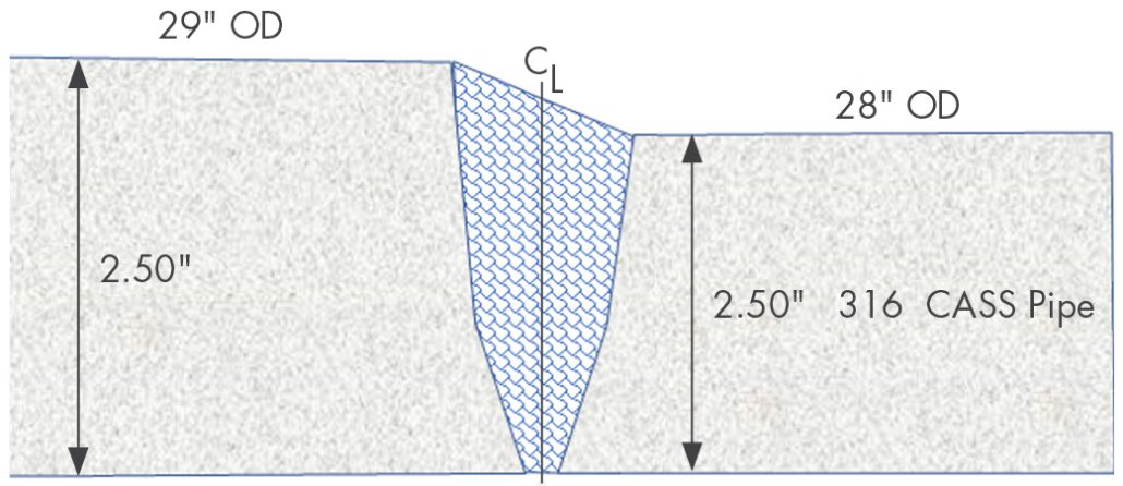
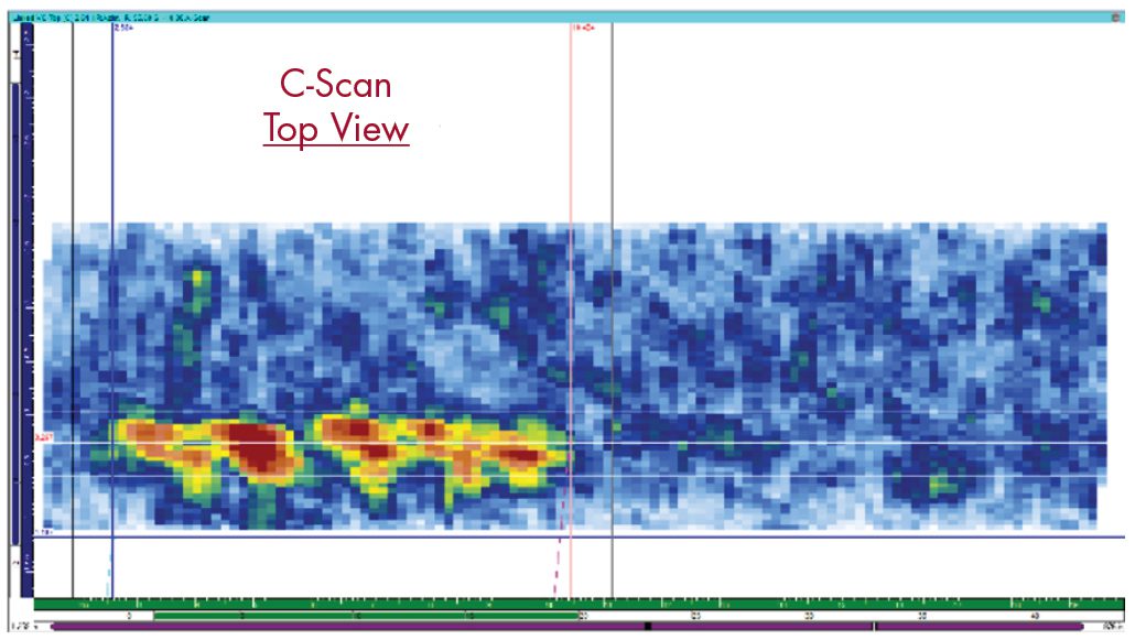
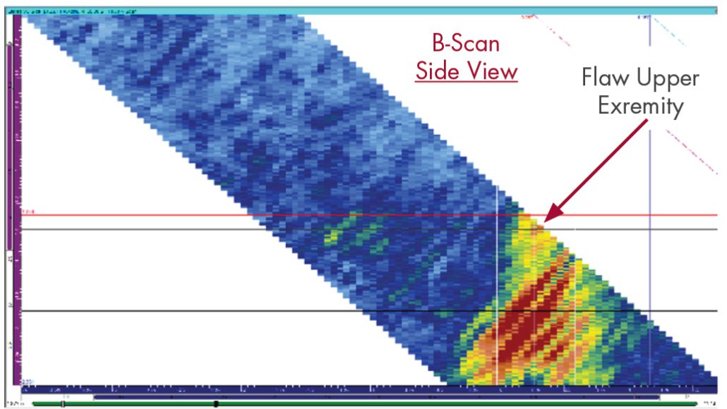
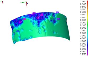
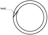
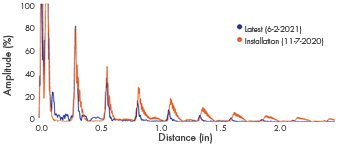
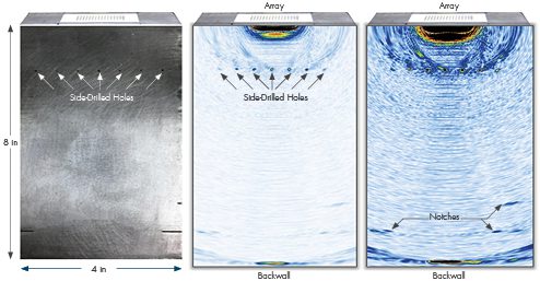
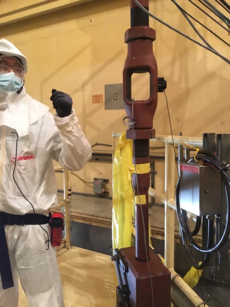
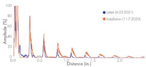
SI offers a suite of engineering and inspection solutions that are designed to help our clients meet their examination commitments while minimizing the associated cost, time, and impact to operations. We work with our clients to determine the required scope of any necessary examinations, based on their Aging Management Program and license renewal commitments, and present a customized inspection approach. Where possible, inspection solutions that can be conducted from outside of the tank are prioritized over approaches that require deploying equipment in the tank. These approaches may include performing pulsed eddy current testing to examine tank walls through insulation or employing guided wave phased array (GWPA) from the tank chime plate to examine the outer annulus of the tank floor (Figure 1).
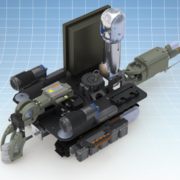
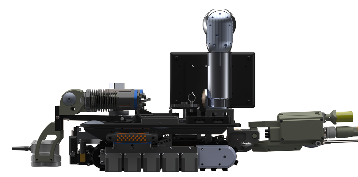
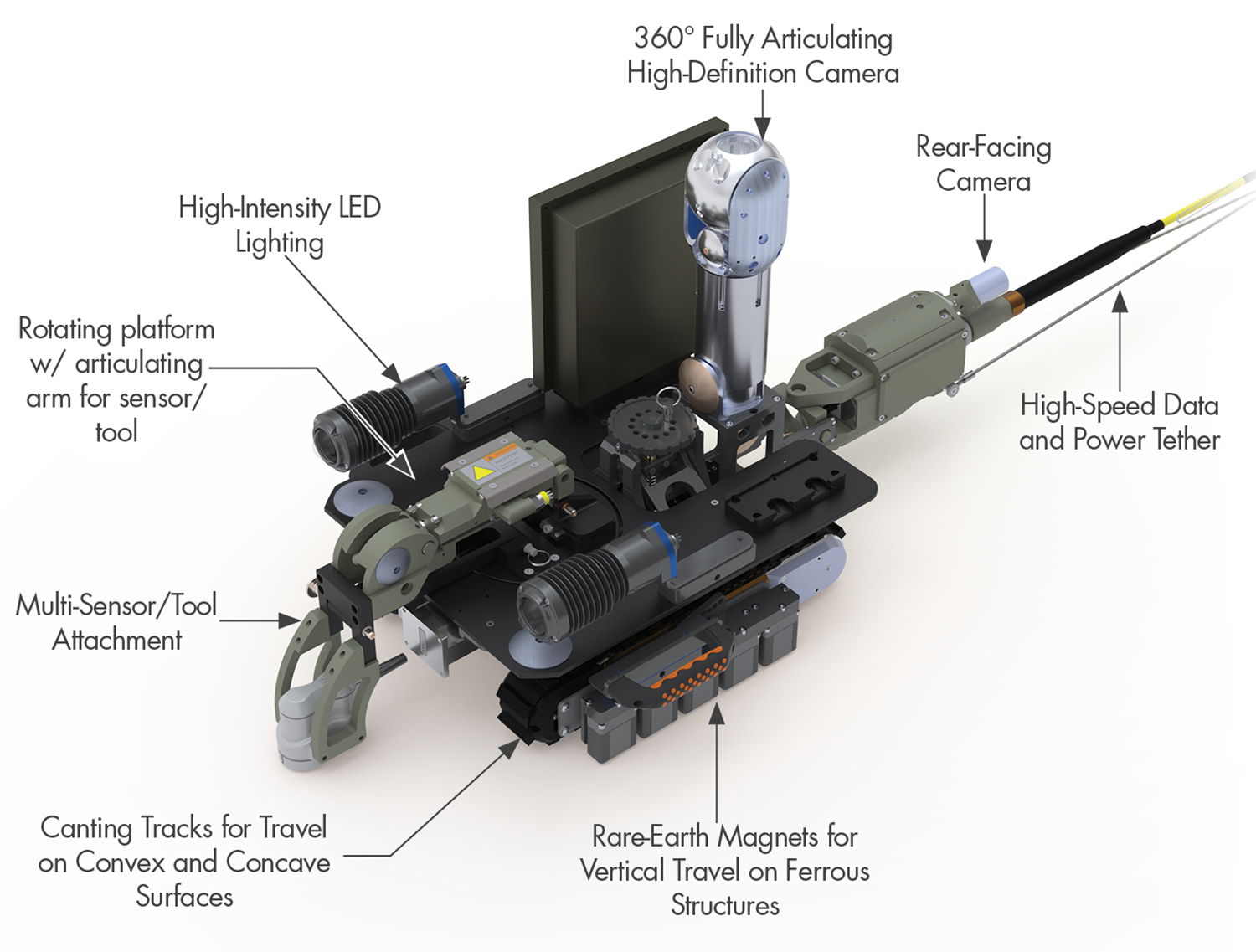
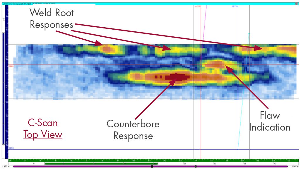
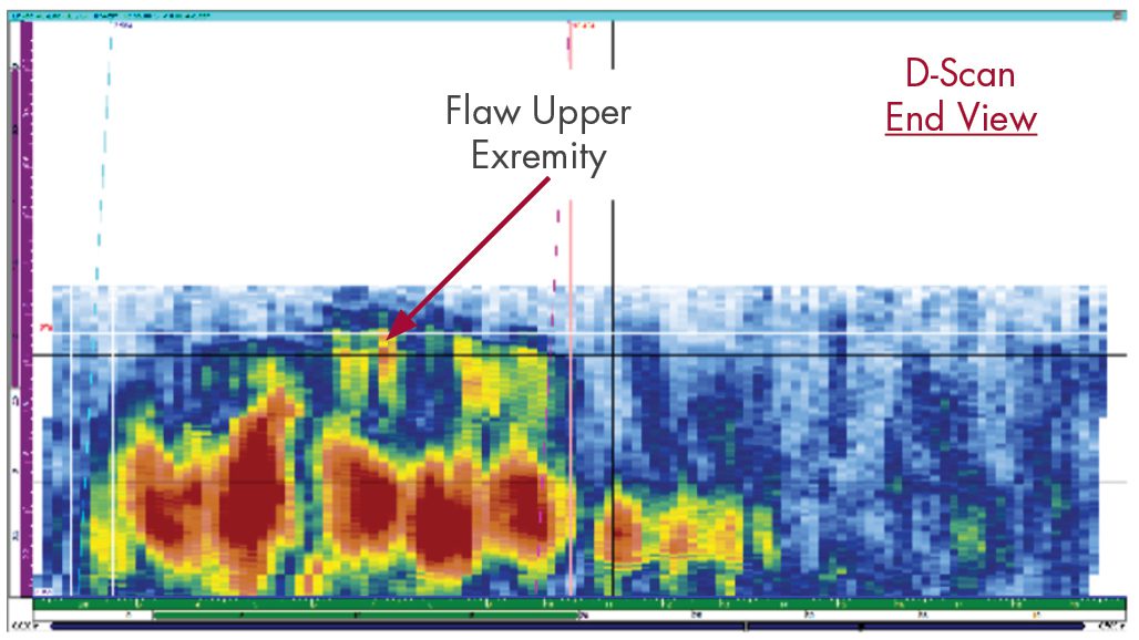
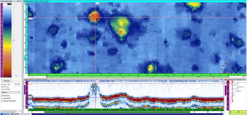
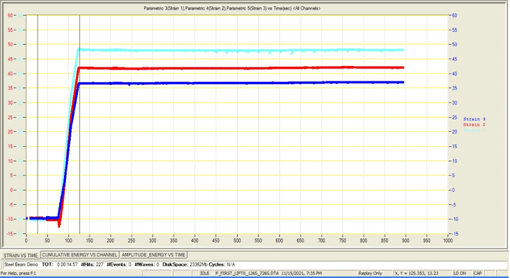
In situations where putting equipment inside the tank is unavoidable, SI has developed a robotic solution that uses a novel technological approach to provide rapid, 100% volumetric coverage with a range of NDE sensors deployed on a relatively basic robotic platform. Rapid, large-area volumetric coverage is obtained by mapping the tank floor with GWPA testing to identify critical areas (Figure 2). These critical areas can then be investigated using high-resolution, non-contact methods, such as electromagnetic acoustic transducers (EMATs) for UT thickness measurements or SI’s dynamic pulsed eddy current technology, SIPEC™, for dirty or lined tanks.
Figure 2. GW Phased Array Tank Floor Inspection
From a deployment perspective, SI’s robotic system is designed to fit through existing tank access points, can scale carbon steel walls, and can quickly switch between a range of sensor types. Additionally, SI has incorporated a proprietary acoustic vehicle positioning system, where sound pulses track the absolute position of the robot at all times, ensuring precision results and the ability to accurately relocate and rescan specific areas for follow-up activities or future inspections. The acoustic positioning system uses a transmitter placed on the robot and a series of receivers placed on the exterior tank wall to track the movement of the robot. With this approach, positioning is not reliant on visual or other optical methods that can be confounded by cloudy, murky, or otherwise opaque liquid and is not subject to encoder error or drift.
Engineering Support Services
Beyond inspection, SI provides integrated engineering support that couples directly with tank inspections. SI’s expertise includes disposition of findings, detailed evaluation of any anomalies, and optional integration with our piping and tank asset management database, MAPPro™. SI engineers are adept at employing detailed FEA models and/or fracture mechanics techniques to assess the acceptability of any observed flaws/defects. For time-critical inspections, engineering handbooks can be developed before the examinations to provide real-time disposition of any findings. Loading inspection results into MAPPro enables risk-ranking utilizing time-proven algorithms, thereby informing future programmatic actions.
Using the advanced deployment and inspection technologies highlighted herein, SI is able to comprehensively inspect and disposition findings from tanks of various sizes while reducing schedule risk and ensuring accurate results.
Tank Inspection NDE Technologies
- Guided Wave Phased Array (GWPA)
- Used to rapidly inspect large areas such as a tank floor.
- Provides 100% volumetric coverage in a minimal amount of time and with minimal surface preparation.
- Identifies critical areas that should be investigated further using more precise examination technology. This follow-up is completed by switching probe heads and conducting targeted quantitative exams.
- Can also be applied from the chime plate on the tank exterior to examine the outer annulus of the tank floor.
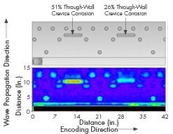
- Electromagnetic Acoustic Transducer (EMAT) Ultrasonic Thickness Testing
- A non-contact (up to 0.25 inches of liftoff) volumetric examination that provides quantitative wall thickness for either carbon or stainless-steel tanks.
- Electromagnetic sensors generate UT for thickness measurements and are electromagnetically coupled, thus eliminating the need for couplant or close contact with the test surface.
- This type of testing is helpful for corrosion mapping where surface prep is not possible or costly or if there is a coating/liner present; additionally, it allows for remote robotic inspections, including those where the probe is submerged.
- SIPEC™ Electromagnetic Thickness Testing
- Proprietary non-contact volumetric examination that works through internal liners and sediment (up to several inches) targeting either carbon or stainless steel.
- Employs a proprietary dynamic pulsed eddy current measurement technique for rapid scanning.
- Higher liftoff, lower resolution option when compared to EMAT UT.


 Structural Integrity (SI) has recently added drones to our toolbox of inspection equipment. Using drones, inspectors are able to complete visual inspections safely and more efficiently. Applications of drones for visual inspections include plant and piping walkdowns, structural inspections and atmospheric corrosion monitoring (ACM) of exposed pipeline.
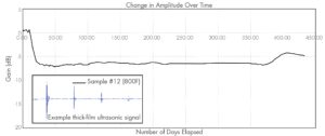
 SI has successfully implemented the initial application of an integrated monitoring solution that provides insight into damage evolution and operational risk using real-time data and automated engineering intelligence. This solution will assist in the optimization of maintenance activities and downtime, helping utilities get the most out of their O&M budgets. “This is a decisive step toward a more modern asset management approach that will lower O&M cost for our clients,” said Steve Gressler, Vice President, SI Energy Services Group, a division of Structural Integrity Associates, Inc. (SI) focused on power plant asset integrity.


 By: Jason Ven Velsor, Roger Royer, and Ben Ruchte