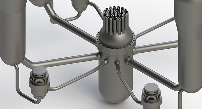
Reactor Vessel Integrity - Fracture Toughness Criteria

News & Views, Volume 50 | Reactor Vessel Integrity

FRACTURE TOUGHNESS CRITERIA

By:  Tim Griesbach and Dan Denis

Reactor Vessel Integrity - Fracture Toughness CriteriaThe integrity of the nuclear reactor pressure vessel is critical to plant safety.  A failure of the vessel is beyond the design basis.  Therefore, the design requirements for vessels have significant margins to prevent brittle or ductile failure under all anticipated operating conditions.  The early vessels in the U.S. were designed to meet Section VIII of the ASME Boiler and Pressure Vessel Code and later Section III.  ASME Section III included requirements for more detailed design stress analyses also included a fracture mechanics approach to establish operating pressure-temperature heatup and cooldown curves and to assure adequate margins of safety against brittle or ductile failure incorporating the nil-ductility reference temperature index, RTNDT. This index is correlated to the material reference fracture toughness, KIC or KIa. 

Radiation embrittlement is a known degradation mechanism in ferritic steels, and the beltline region of reactor pressure vessels is particularly susceptible to irradiation damage.  To predict the level of embrittlement in a reactor pressure vessel, trend curve prediction methods are used for projecting the shift in RTNDT as a function of material chemistry and fluence at the vessel wall.  Revision 2 of this Regulatory Guide is being used by all plants for predicting RTNDT shift in determining heatup and cooldown limits and hydrostatic test limits.

READ MORE

News & View, Volume 46 | Application of Probabilistic Flaw Tolerance Evaluation Optimizing NDE Inspection Requirements

News & Views, Volume 46 | Application of Probabilistic Flaw Tolerance Evaluation Optimizing NDE Inspection Requirements

By:  Christopher Lohse

News & View, Volume 46 | Application of Probabilistic Flaw Tolerance Evaluation Optimizing NDE Inspection RequirementsThere have been several industry initiatives to support optimization of examination requirements for various items/components (both Class 1 and Class 2 components) in lieu of the requirements in the ASME Code, Section XI.  The ultimate objective of these initiatives is to optimize the examination requirements (through examination frequency reduction, examination scope reduction, or both) while maintaining safe and reliable plant operation.  There are various examples of examination optimization for both boiling water reactors (BWRs) and pressurized water reactors (PWRs).  Each of these technical bases for examination optimization relies on a combination of items.  The prior technical bases have relied on: (1) operating experience and prior examination results as well as (2) some form of deterministic and/or probabilistic fracture mechanics.   For BWRs, the two main technical bases that are used are BWRVIP-05 and BWRVIP-108.  These technical bases provide the justification for scope reduction for RPV circumferential welds, nozzle-to-shell welds, and nozzle inner radius sections.  For PWRs, the main technical basis for RPV welds is WCAP-16168.  These technical bases are for the RPV welds of BWRs and PWRs which represent just a small subset of the examinations required by the ASME Code, Section XI.  Therefore, the industry is evaluating whether technical bases can be optimized for other components requiring examinations. 

READ MORE

News & View, Volume 46 | Acoustic and Blowdown Load Calculations for Reactor Internals

News & Views, Volume 46 | Acoustic and Blowdown Load Calculations for Reactor Internals

By: Matthew Walter

News & View, Volume 46 | Acoustic and Blowdown Load Calculations for Reactor InternalsAs part of the general design criteria for nuclear power plants, the primary structures and systems of the plant must be designed to handle postulated accident events, including the dynamic effects of postulated pipe ruptures. For a Boiling Water Reactor, analyzed events include various accident conditions in the recirculation piping, including a Loss of Coolant Accident (LOCA). One postulated LOCA event is assumed to be an instantaneous double-ended guillotine break of the recirculation line. This event causes several loads to be imparted on the reactor vessel, attached piping, and reactor internal components. [Some loads such as jet impingement, annulus pressurization, and pipe whip impart loads on the outside of the reactor vessel and the attached piping.][ Other loads, including flow-induced drag and acoustic loads, transmit loads inside the vessel on critical components such as jet pumps, core shroud, and the shroud support structure.] Figure 1 shows the pipe and resulting loads.

READ MORE

News & View, Volume 45 | Interval Relief from RPV Threads in Flange Examination Requirements

News & Views, Volume 45 | Interval Relief from RPV Threads in Flange Examination Requirements

By:  Scott Chesworth

News & View, Volume 45 | Interval Relief from RPV Threads in Flange Examination RequirementsASME Code Section XI requires that the RPV Threads in Flange component (Category B-G-1, Item Number B6.40, see Figure 1) be inspected each inspection Interval using volumetric examination.  However, there is general agreement that the inspection does not contribute to the overall safety of the RPV.  Industry experience indicates that these examinations have not been identifying service-induced degradation and that they have negative impacts on worker exposure, personnel safety, and outage critical path time.  Savings from the elimination of this inspection can be applied to other more meaningful inspections of other more risk-significant plant components.

EPRI Report 3002007626 (March 2016) provides the basis for eliminating the RPV Threads in Flange examination requirement.  This report includes the results of an industry survey in which 168 units provided the status of their RPV Threads in Flange examination, as well as insight into the impacts of conducting these examinations.

READ MORE

News & View, Volume 43 | LatitudeUsing Falcon to Develop RIA Pellet-Cladding Mechanical Interaction (PCMI) Failure Criteria

News & Views, Volume 43 | Using Falcon to Develop RIA Pellet-Cladding Mechanical Interaction (PCMI) Failure Criteria

By:  John Alvis

IntroductionNews & View, Volume 43 | LatitudeUsing Falcon to Develop RIA Pellet-Cladding Mechanical Interaction (PCMI) Failure Criteria
The goal to achieve higher fuel rod burnup levels has produced considerable interest in the transient response of high burnup nuclear fuel.  Several experimental programs have been initiated to generate data on the behavior of high burnup fuel under transient conditions representative of Reactivity Initiated Accidents (RIAs).  A RIA is an important postulated accident for the design of Light Water Reactors (LWRs). It is considered the bounding accident for uncontrolled reactivity insertions.

The initial results from RIA-simulation tests on fuel rod segments with burnup levels above 50 GWd/tU, namely CABRI REP Na-1 (conducted in 1993) and NSRR HBO-1 (conducted in 1994), raised concerns that the licensing criteria defined in the Standard Review Plan (NUREG-0800) may be inappropriate beyond a certain level of burnup.   Figure 1 is an example of a typical high burnup fuel cladding showing the oxidized and hydrided cladding of higher burnup fuel rods.  Figure 2 shows the typical radial crack path in oxidized and hydrided cladding, subjected to RIA simulation tests.  As a consequence of these findings, EPRI with the assistance of the Structural Integrity’s Nuclear Fuel Technology Division (formally ANATECH) and other nuclear industry members conducted an extensive review and assessment of the observed behavior of high burnup fuel under RIA conditions.  The objective was to conduct a detailed analysis of the data obtained from RIA-simulation experiments and to evaluate the applicability of the data to commercial LWR fuel behavior during a Rod Ejection Accident (REA) or Control Rod Drop Accident (CRDA).  The assessment included a review of the fuel segments used in the tests, the test procedures, in-pile instrumentation measurements, post-test examination results, and a detailed analytical evaluation of several key RIA-simulation tests.

READ MORE