News & Views, Volume 52 | Forecasting the Life of a Mass Concrete Structure, Part Two

A CASE STUDY FROM THE FERMILAB LONG BASELINE FACILITY

By:  Keith Kubischta and Andy Coughlin, PE, SE

REFRESHER OF PART 1
From part one of the article (see News and Views Volume 51), we looked at the performance of a unique tubular mass concrete structure – the decay region of Fermilab’s Long Baseline Neutrino Facility – under complex thermal loading and thermal expansion. In the process of colliding subatomic particles in an accelerator and beaming them across the country underground, the facility contends with a massive amount of heat, an active nitrogen cooling system to remove energy, and shielding necessary for the surrounding environment. As we discussed in Part 1, Structural Integrity assisted with the design of the concrete structure by calculating the pertinent structural and thermal behavior under normal operation.  Now for Part 2, we focus on forecasting the future life of the structure using advanced capabilities in analysis and delve into the actual life of this concrete structure while considering the construction process, a 30 year planned cycle of life, and how these influence planning for structural monitoring systems. In doing so, we attempt to answer a larger question: What can we learn from this structure that could be applied to other past and future structures?

These methods are not only applicable to new structures.  Armed with the knowledge we can gain from record drawings, visual inspection, and non-destructive examination, SI is able to predict the life of concrete structures, new and old, giving key insights into their behavior in the future.

Figure 1. Fermilab Long Baseline Neutrino Facility (source https://mod.fnal.gov/mod/stillphotos/2019/0000/19-0078-02.jpg)
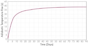
Figure 2. Adiabatic Temperature Rise for Concrete Placement

HEAT OF HYDRATION
In understanding the life of a structure, we must first start at the beginning as the concrete is first poured where another heat transfer takes place. Contrary to popular belief, concrete does not “dry”, rather it “bakes” itself during the curing process. As concrete is poured, it begins heating up internally through an exothermic hydration reaction between water and cement. The effect of the heat of hydration can usually be ignored in typical thin-walled structures. In larger mass concrete structures, however, the heat generation can cause significant degradation and built-in damage that can affect the structural performance throughout the entire life of the facility. 

A secondary subroutine as part of the ANACAP models is used for heat of hydration specific for construction analysis to convert the temperature rise into volumetric heat generation rate for thermal analysis. When heat is trapped deep inside the structure and can’t escape, the concrete exhibits a temperature rise similar to the curve in Figure 2, which is a function of the concrete mix proportions.
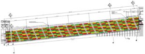
Figure 3. Placement Sequence of 164 Concrete Pours

CONSTRUCTION ASSESSMENTS
For the operating conditions covered in Part 1, the coupled 3D thermal stress analyses performed on this project were thermal conduction steady-state analyses. Construction of such a large concrete structure is subjected to additional requirements, and a Nonlinear Incremental Structural Analysis (NISA) was performed to evaluate the structure under the construction loadings. Herein, the thermal analysis during the concrete placement sequence requires a transient numerical solution methodology. This thermal analysis was used to monitor additional requirements for temperature during concrete placement, and a mechanical NISA study monitored the movement of the central cooling annulus vessel. The complete NISA coupled thermal-stress analysis simulated the entire construction phase over the period of a year and a half of the planned construction schedule. To accomplish this, the model was segmented into 164 concrete pours, each one activated (turned on) within the model on a specific day outlined in a construction schedule, as shown in Figure 3. As the concrete is poured on its specific day, the heat of hydration begins to heat up the internals of the concrete, the outside ambient temperature pulls the heat away from the concrete, and formwork insulates the heat transfer temporarily before being removed. As each new concrete segment is poured (activated in the simulation) it begins a new heat cycle, shedding heat into surrounding segments, changing surfaces that are exposed to air, or where the formwork is located. Upon completion of the thermal NISA study, Structural Integrity could advise on peak temperatures of each pour (Figure 4), compare internal to external temperatures and make optimal recommendations for insulation to keep the concrete from cooling too fast.
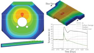
Figure 4. Thermal Views and Monitoring of Concrete Placement Temperatures

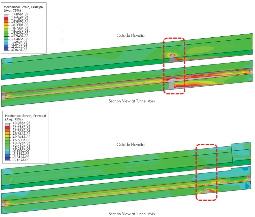
With the thermal NISA study completed, we then coupled the thermal with the mechanical stress analysis following a similar procedure. The model was broken up into the same 164 segments, with the reinforcement separated into individual segments. As a segment was poured, its weight was first applied as pressure on surrounding segments before the segment cured enough and took load. Formwork was considered a temporary boundary condition (simulated with stiff springs): activated then removed when appropriate. The concrete internal reinforcement was activated with each concrete segment. The cycles continue with each additional segment added. The concrete material for each segment had its own values for aging, creep, shrinkage, and thermal degradation for when the concrete was placed. The effect of creep and shrinkage could be significantly different for concrete poured on the first day and concrete that is poured a year later.  Mechanical tensile strain, a proxy for cracking, was plotted as shown in Figure 5.

A critical issue of concern was the steel annulus structure at the center of the concrete tunnel. The entire steel structure was placed prior to concrete being poured around it. The steel structure was affected by the thermal and mechanical loads of each concrete pour. Structural Integrity showed this structure “breathing” as thermal/mechanical loads pass from each concrete pour into the steel structure. Armed with a complete picture from the NISA stress analysis, Structural Integrity could show the animation of annulus movement, check the out-of-roundness, and advise on reinforcement placement. 
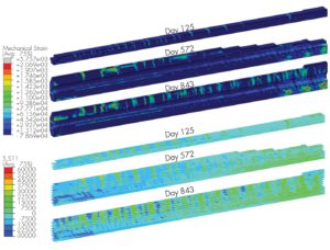
Figure 5. Concrete Mechanical Strain (i.e., Cracking) and Rebar Stress During NISA Construction

LIFECYCLE ASSESSMENTS
During the design phase, reinforced concrete structures are typically designed for a bounding range of expected loads, to include thermal load cycles, periodic live load variations, and/or vibration from mechanical equipment. Up to this point, the design phase analysis started from a “pristine” uncracked structure and applied the expected load with the beam and cooling at full power. Seldom is the cumulative impact of cyclic loading considered for the expected service life of the structure. Structural Integrity, having performed the NISA study, now had significantly more accurate state of the structure with expected cumulative damage already built-up. This gave us the unique opportunity to extend the analysis from the current state through the lifecycle of the structure, comparing the “pristine” to the “cumulative” case.

The expected life of the structure is 30 years of operations with the beam running for no more than nine months a year and three months off. These cycles are grouped together in either seven- or five-year blocks with a rest period of two years for maintenance or upgrades in between. The experiment starts small, ramping up the power to half the total output for the initial seven years. For the lifecycle assessment, time is still a critical element, not just for properties of concrete affected by time but the physical computational time. The transient thermal analysis would be too time intensive to run over the 30 years of life that we want to observe. To simulate the thermal cycles, the beam steady-state thermal response was calculated at each peak power level. This provided different thermal states of power, which the mechanical analysis could switch on or off as needed and interpolate between them to give a simulated ramp of power. The computational time could then be utilized on the mechanical stress lifecycle assessment.
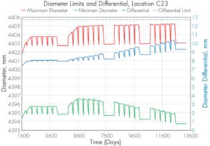
Figure 6. Out-of-Roundness Check through Lifecycle, Ratcheting Effect of Power Cycles

With the completion of the lifecycles analysis, Structural Integrity could once again provide valuable information to the researchers and designers: deformations of the entire structure, deformations of the annulus, out-of-roundness of the annulus (Figure 6), estimates of crack width, etc.

Most importantly, we can answer and show comparisons between the designed load from a “pristine” model analysis to those from the “cumulative” analysis.

Even prior to the lifecycle assessment, the cumulative damage at the end of the NISA study signaled different behavior in the expected cracking (Figure 7). From the construction process, the concrete showed cracking near the boundaries between each concrete pour. These developed due to the natural thermal cycling of the construction process. The lifecycle thermal loading continued to push and pull the structure adding to the already existing cracks. Previously, the boundary point between the fixed rail and sliding rail section concentrated the thermal loading to induce significant cracking. Now the stress will be more evenly distributed throughout the upstream section. The cracking during construction provided natural thermal breaks along the whole length of the structure.
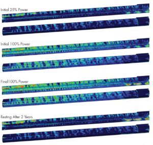
Figure 7. Concrete Strains at Various Point in Structures Lifecycle

HEAT DISPERSAL
SI then turned toward an additional question, where does all this excess heat go as the beam is cycling power? The shielding concrete is still heating up to over 60 degrees Celsius at the exposed surfaces. The air around the shielding concrete is trapped by the decay tunnel and venting conditions are unknown. We would need to produce a calculation based on the transfer of heat from the shielding concrete to the surrounding air/access tunnel, to the decay tunnel itself, and then the surrounding soil. Assuming the worst-case scenario, a point was selected along the length of the tunnel that produces maximum temperatures in the concrete. The cross section at this point is turned into a 2D model for use in a thermal analysis conducted as steady-state and transient to explore the heat transfer into the surrounding sections. A temperature profile of the decay tunnel wall was used to check its design from the thermal gradients, shown in Figure 9. The temperature of the air space between the structures can be monitored help in planning for when the tunnel can safely be accessed.

ONLINE MONITORING
Engineers at SI are always eager to add data to our models.  As this structure is constructed and put into service, the actual construction and startup sequence is likely to change, allowing for the model to be rerun and the lifecycle projection recalculated.  Furthermore, data from temperature sensors and crack monitoring gauges could potentially help calibrate the model based on observed conditions to improve the accuracy of our projections moving forward.  This methodology is applicable today to existing aging concrete structures where the lifecycle projection can be calibrated to existing observed conditions and data from online monitoring and non-destructive examinations.
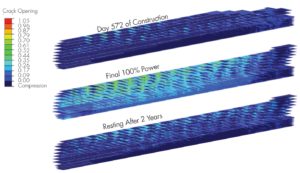
Figure 8. Crack Width Estimation Based on Reinforcement Strain

CONCLUSIONS
Structural Integrity successfully developed expanded capabilities to model thermodynamics for the energy deposition and nitrogen cooling system. SI pushed the capabilities of our concrete model to capture over 30 years of construction and operations. Along the way, SI showed that our advanced modeling, combined with our advanced concrete model, positively influenced the design of the structure, and heavily supported the design and research teams with valuable information. The robustness of the calculation showed that SI is the present and future of concrete structure analysis.

SI demonstrated that our advanced modeling, combined with our advanced concrete model, positively influenced the design of this structure and heavily supported both the research and design teams with valuable information.
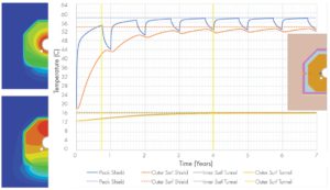
Figure 9. 2D Thermal Results of Decay Tunnel, Air Access Space, Shield Tunnel Walls, and Surrounding Soil

Get News & Views, Volume 52

Structural Integrity Associates | News and Views, Volume 51 | Managing Forecasting the Life of a Mass Concrete Structure

News & Views, Volume 51 | Forecasting the Life of a Mass Concrete Structure, Part One

A CASE STUDY FROM THE FERMILAB LONG BASELINE FACILITY

By:  Keith Kubischta and Andy Coughlin, PE, SE

Structural Integrity Associates | News and Views, Volume 51 | Managing Forecasting the Life of a Mass Concrete Structure

All around us is aging concrete infrastructure. From the dams holding back water, to the nuclear power plants creating carbon free electricity, to the foundations of our homes and offices. Though many advances have been made in the design of concrete structures, how do we know these structures will stand the test of time. Can we see the future of a concrete structure? Can we know the damage built into a structure during construction, normal life, and extreme events?
Answer:  Yes we can.

Background

In Batavia, Illinois a facility being built that is the first of its kind in the world. Fermilab’s Long Baseline Neutrino Facility will accelerate protons using electromagnets up to incredible speeds in a particle accelerator. After traveling through the campus, the particles are redirected to a graphite target where the collision breaks them into their component particles: pions and muons. These components decay and are segregated off. What is left is believed to be the building blocks of the universe: neutrinos, which can pass undisturbed through matter. A beam of neutrinos passes through near detectors and travels over 800 miles underground to a detection facility in an old mineshaft at Sanford Underground Research Facility in South Dakota, a facility that can also detect neutrinos hitting the earth from exploding stars.

Figure 1. Fermilab Long Baseline Neutrino Facility (source https://mod.fnal.gov/mod/stillphotos/2019/0000/19-0078-02.jpg)

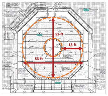
After the graphite collision what is left behind has the potential to create some harmful biproducts such as tritium, or hydrogen-3, which needs to be kept out of the surrounding atmosphere, soil, and ground water. This occurs in the decay region slightly downstream from the target complex, which is 630-ft long concrete tunnel with 18 feet of concrete surrounding the beam line. Exiting the decay tunnel any leftover particles are absorbed downstream in the absorber hall. 

Figure 2. Overview of Decay Region

The tunnel of the decay region houses an octagonal shielding concrete structure to provide shielding for the byproducts. This octagonal structure is over fifty feet tall and wide with 42,000 cubic yards of concrete, enough concrete to construct a baseball stadium. At the center of the tunnel is a double walled stainless steel pressure vessel charged with helium on the inside and a chilled flow of nitrogen gas within the annulus. The octagonal shielding concrete structure is surrounded by an access area to inspect the structure, the outer decay tunnel walls, and the surrounding soil.

Figure 3. Typical Decay Region Tunnel Cross Section

The octagonal shape of the shielding concrete was not always so octagonal. Starting off with small steps, Structural Integrity demonstrated advanced capabilities to model thermal structural behavior of mass concrete, while developing and expanding on existing capabilities. SI’s positive impact on the early stages of the project earned us a larger role where we displayed additional capabilities to positively influence the design of the structure.

SI followed the design progression and answered some critical questions, such as: 

  1. Will the decay region be within acceptable temperatures when subject to the extreme energy deposition from the decaying particles? 
  2. What thermal expansion joints will be required to prevent cracking, and movement of the underground structures in a harmful way? 
  3. How can we best optimize the reinforcement of such a massive structure? 

SI answered these questions and more through expert analysis, expanding our capabilities through proprietary simulation ranging from earlier design concepts, construction stages, and up to including a 50-year design life of the structure. 

Part One of this article will look at the influence our work had of the design of the massive structure and the benefits of “seeing the cracks” before they happen.

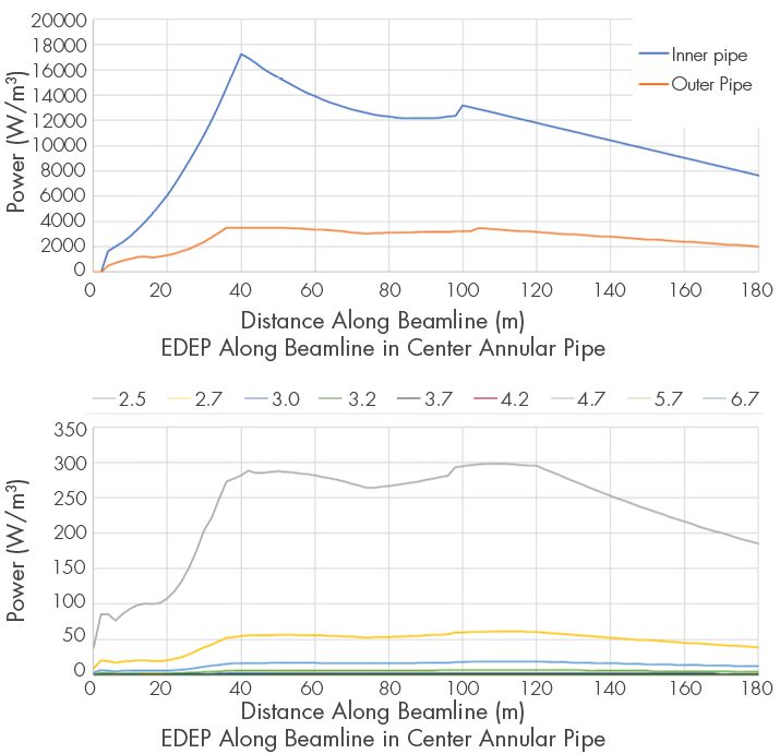
Figure 4. EDEP Axial and Radial Distribution along the Beamline

Energy Deposition and Cooling Thermodynamics

Concrete that gets too hot can vaporize the pore water and even break apart. The transfer of heat in concrete is a critical component of the analysis and is both added to the structure and removed. Thermal loading was provided by Fermilab in the form of volumetric energy deposition (EDEP) on the concrete and steel based on particle physics software simulation program MARS. The distribution of EDEP varies both radial outward from the beamline and compounded by its positioning along the length of the tunnel. SI would need to convert the distribution into a subroutine of distributed flux for use by the analysis program. The distribution was first translated for use in 2D analysis, expanded into 3D space, and then rotated in coordinate space to account for the slope of the beamline. With the EDEP adding heat to the system, chilled nitrogen is needed to remove heat.

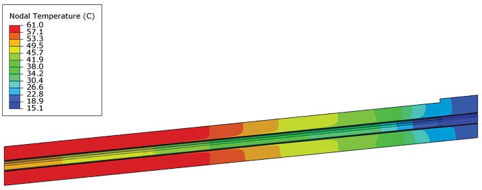
Figure 5. Accurate Thermal Distribution along the Decay Tunnel Shielding Concrete Structure.

A bit of “back-to-school” was needed to solve the thermodynamic problem. The heat transfer coefficient and temperatures of the nitrogen gas cooling system were calculated using classical methods on convection relationships in annular spaces. With the known EDEP into the concrete and steel, which dominates in regions closer to the center, it was decided as a design condition that all heat be taken by the nitrogen to obtain the outflow temperature of the nitrogen gas. The nitrogen temperature was calculated in 10m increments along the annular pressure vessel and at outflow based on an energy balance equation. The heat transfer coefficient was calculated using three different empirical relationships for Nusselt number utilizing the lower bound conservative estimate in the analysis. Our efforts created an accurate model in 3D space of the heat transfer into the shielding concrete. As a result of the nitrogen cooling system, we were able to keep concrete temperatures below the limit of 110 degrees Celsius. With the thermodynamic problem solved, SI progressed, coupling the solution to the mechanical stress model.

Concrete Capabilities

If there is one thing concrete is guaranteed to do, it is to crack. SI’s proprietary concrete constitutive model, ANACAP, is designed to predict concrete cracking and preform under various states of those cracks opening and closing. The behavior of concrete is highly nonlinear with low tensile strength, shear stiffness and strength that depend on crack widths, and plasticity compression. The main components of the concrete model utilized in the design phase analyses are tensile cracking, post-cracking shear performance, and compressive yielding when the compressive strength is reached. The use of the ANACAP concrete model has been validated and verified through 30 years of use and a key component for the nonlinear assessments.

Figure 6. Stepped vs Octagonal Cross Section, Thermal Distributions and Concrete Strain (Cracking)

Influence on Design

Accurate modeling of thermodynamics / thermal analysis, coupling with the mechanical model / stress analysis, and the capabilities of the nonlinear constitutive concrete model allow for the simulation of a full 3D model of the shielding concrete under full power operations. The design team sought to minimize the cracking of the structure, monitor elongations and other movements affecting the beam line, and design connections at the structure boundaries. SI coordinated with research and design teams to facilitate several cross-section iterations with different shapes and layers of shielding. Each design iteration was analyzed to demonstrate the benefits or consequences. An early iteration of the shield concrete cross-section was a stepped block shape. The corners of the stepped cross-section displayed the potential for cracking. SI addressed this potential design trait through influencing the development of the octagonal section shape. This optimization allows the design to minimize the amount of reinforcement needed to control cracking.

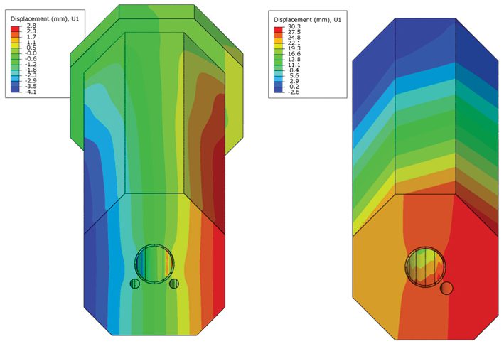
Figure 7. Lateral Displacements of Single Return Pipe and Dual Return Pipe

In addition to the cooling annulus at the center of the structure, there are the return ducts for the system to bring the nitrogen back to the target complex facility. The design initially used four return pipes spread out at four different corners. In one iteration the design team attempted to reduce the four return ducts to one larger return pipe to reduce the concrete volume required for shielding. The design iteration with one return duct was attempting to reduce costs by reducing the overall amount of concrete needed. Our calculations quickly identified unintended consequences. The asymmetrical shape was creating displacements along the transverse horizontal direction, pushing the beam alignment off-center by over an inch (~30 mm). The shape was quickly updated to be symmetric with two return pipes. 

From room temperature to 60 degrees Celsius, concrete is going to expand. Traditional thermal breaks cannot be utilized in this structure to maintain continuity and provide shielding. The design needed to allow the structure to expand at the downstream end. Most of the structure is supported by rails where it was designed to freely slide at the bottom of the octagonal section during the expansion phase. A section of these rails needs to be fixed at the upstream end where it was designed to resist the gravity of the structure along the slope. SI provided valuable design influence with where the fixed rails were to be positioned as the thermal loading created immense stress at the location between the fixed boundary and sliding boundary. In the original position, SI’s calculations identified a concentrated area of cracking. To minimize the amount of cracking and additional reinforcement needed, SI proposed moving the position of restraint towards the cool / upstream end of the tunnel.

Figure 8. Effect of Fixed Rail Boundary Condition Position on Strain.

How do you stop 42,000 cubic yards of concrete from expanding?

Answer:  You Don’t. 

Conclusions

Structural Integrity successfully developed expanded capabilities to model thermodynamics for the energy deposition and nitrogen cooling system. SI used the capabilities of our concrete model to influence the structural design by “seeing the cracks” before they happen, making design adjustments, and reducing reliance on additional reinforcement. SI was able to give key insights for the concrete structure and potential cost savings through optimization.

Part Two of this article will look at the life of the structure form the day concrete is first poured to 30 years of power cycles. Delving into the future to see this structures test of time and monitoring methods to see if our predictions come true.

Get News & Views, Volume 51

American Society of Civil Engineers, ASCE

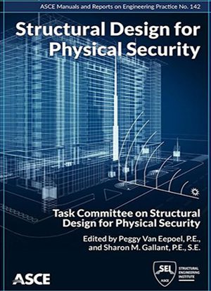
Structural Design for Physical Security

Structural Integrity’s Own, Andy Coughlin published by American Society of Civil Engineers, ASCE

American Society of Civil Engineers, ASCEAndy Coughlin’s work has been published in the ASCE Structural Design for Physical Security: State of the Practice. The Task Committee on Structural Design prepared the publication for Physical Security of the Blast, Shock, and Impact Committee of the Dynamic Effects Technical Administration Committee of the Structural Engineering Institute of ASCE.  Andy wrote Chapter 10 on Testing and Certification for Physical Security and assisted on several other chapters.

Structural Design for Physical Security, MOP 142, provides an overview of the typical design considerations encountered in new construction and renovation of facilities for physical security. The constant change in threat tactics and types has led to the need for physical security designs that account for these new considerations and anticipate the environment of the future, with flexibility and adaptability being priorities. This Manual of Practice serves as a replacement for the 1999 technical report Structural Design for Physical Security: State of the Practice and is intended to provide a roadmap for designers and engineers involved in physical security. It contains references to other books, standards, and research.

Topics include

  • Threat determination and available assessment and criteria documents,
  • Methods by which structural loadings are derived for the determined threats,
  • Function and selection of structural systems,
  • Design of structural components,
  • Function and selection of window and facade components,
  • Specific considerations for retrofitting structures,
  • Testing methodologies, and
  • Bridge security.

This book will be a valuable resource to structural engineers and design professionals involved with projects that have physical security concerns related to explosive, ballistic, forced entry, and hostile vehicle threats.

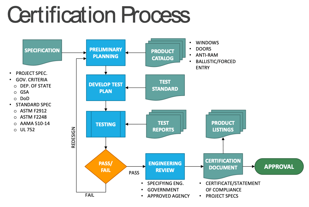
Of particular note is the publication of the process by which products can be tested and certified to achieve physical security performance in blast, ballistics, forced entry, and vehicle impact.  Often unclear or overly specific requirements hamper the application of quality products which protect people and assets from attack.  The certification process below shows how approved agencies, like SI’s TRU Compliance, play a role in testing, evaluating, and selecting products for use in critical physical security applications, rather than relying solely on the claims of the manufacturers.  TRU’s certification program is the first of its kind to receive IAS Accreditation for the certification of physical security products.Certification Process

News & Views, Volume 49 | Code Compliance and the Modular Construction Trend

News & Views, Volume 49 | Code Compliance and the Modular Construction Trend: What Manufacturers Need to Know to Comply with Building Codes

By:  Andy Coughlin, PE, SE

News & Views, Volume 49 | Code Compliance and the Modular Construction Trend

The modular construction industry is projected to grow globally at an annual rate of 6.9%, outpacing the growth of traditional construction.1  Modular construction has many advantages over traditional building methods, including improved quality control and shorter project durations. Factory-built systems are constructed in controlled environments with equipment and materials that are not feasible at congested job sites, and project schedules can be shortened when factory work and field work are performed in parallel.

However, modular projects may stumble without proper forethought: when fabrication takes place in a factory away from the jobsite, the building officials, inspectors, and engineers can have less oversight and less recourse to implement changes if issues are discovered in the field.  Code compliance may also be an issue when systems are designed by factory engineers rather than the engineer of record.  To mitigate these potential pitfalls, careful planning is required at the start of the project.

MORE

News & View, Volume 46 | TRU Compliance Achieves Accreditation as a Product Certification Body

News & Views, Volume 46 | TRU Compliance Achieves Accreditation as a Product Certification Body

By: Andy Coughlin

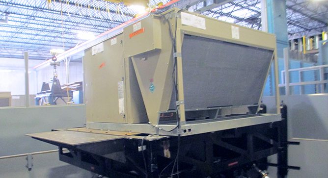
News & View, Volume 46 | TRU Compliance Achieves Accreditation as a Product Certification BodyTRU Compliance, a division of Structural Integrity Associates, announced in March the achievement of accreditation from the International Accreditation Service (IAS) as a product certification body for seismic, wind, and blast/physical security performance of nonstructural components. According to the International Accreditation Service, TRU Compliance is the second company to be certified for Seismic performance of non-structural components and the first company to be certified for Wind and Blast/Physical Security performance.
“This is a significant milestone for Structural Integrity and our certification agency, TRU Compliance,” Chris Larsen, Vice President of Critical Structures at Structural Integrity comments. “The accreditation further validates our robust program as well as our comprehensive approach, which not only meets the stringent guidelines of the ISO standards but offers our customers a full scope solution for product certification”.

READ MORE

News & View, Volume 45 | Proving Performance What Distinguishes an ISO-Compliant Product Certification Agency?

News & Views, Volume 45 | Proving Performance – What Distinguishes an ISO-Compliant Product Certification Agency?

By:  Andy Coughlin

News & View, Volume 45 | Proving Performance What Distinguishes an ISO-Compliant Product Certification Agency?Whether it’s fair-trade coffee, sustain-ably harvested lumber, energy efficient appliances, or other certified products, consumers and companies look for products that have high standards of origin, production, and performance.  Structural Integrity Associates’ TRU Compliance mark is no different.  Our mark shows buyers a product has undergone rigorous assessment for seismic, wind, and blast performance to nationally recognized standards.   
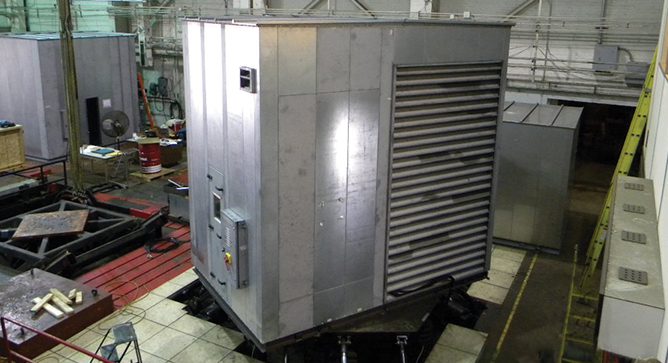
However, not all agencies conform to the internationally recognized set of standards that govern a product certification agency, allowing it to be impartial, objective, and accountable to the public.  The standard ISO/IEC 17065 Conformity assessment — Requirements for bodies certifying products, processes and services spells out requirements that make agencies like TRU Compliance accountable to its clients and to the public.  The requirements in TRU Compliance’s Certification Manual are broad, but they generally fall into the three categories below.

READ MORE

News & View, Volume 43 | TRU Compliance- The Standard for Seismic, Wind, and Blast Certification

News & Views, Volume 43 | TRU Compliance: The Standard for Seismic, Wind, and Blast Certification

By:  Andy Coughlin

About TRU COMPLIANCE

News & View, Volume 43 | TRU Compliance- The Standard for Seismic, Wind, and Blast CertificationAs the product certification arm of Structural Integrity, TRU Compliance stands for safety and code compliance when failure is not an option. Our clients manufacture cutting edge products that push the limits of operational performance and efficiency in many industries. We help them achieve continued performance during earthquakes, high wind events, explosions, and a host of other extreme events.

At TRU Compliance, we believe that achieving code compliance in these areas should not be complicated. So, we continually invest in the development of innovative systems and approaches to simplify the lives of our clients and deliver efficient and transparent results, every time.

TRU Compliance is a recognized leader in Seismic, Wind & Blast product certification. We are a full-service product certification agency executing project specific and product line approvals for a range of code requirements. The TRU Compliance team has been providing product certification services since 2008 and recently joined forces with Structural Integrity in May 2017, thus expanding our resources and reach.

READ MORE