News & Views, Volume 51 | Optical Microscopy Applications and Benefits
By: Clark McDonald
In the world of metallurgical failure analysis, areas of interest on broken parts can be colorful or drab, three-dimensional or flat, and most importantly, very big or very small. A big part of failure analysis work is telling the story, explaining the failure mode, or in some cases, showing that critical piece of evidence that explains why a metal component has failed. From wide-angled lenses to extremely high magnification scanning electron microscope imagery, documentation of failed components is a big part of the presentation.
In this edition of Structural Integrity’s Lab Corner, we wanted to provide some interesting content related to that middle-of-the-road region of magnification; closer than macro-photography but farther away than the 100X to 5000X magnifications that cover most of the applications requiring scanning electron microscopy. In other words, the comfortable world of optical microscopy, where colors, shapes, and even surface textures are part of the story. To do this, we’ve chosen some images that show the usefulness of quality optical microscopic documentation. Each of the provided examples include a brief description along with specific comments on the benefits of optical microscopy for that project, where applicable.
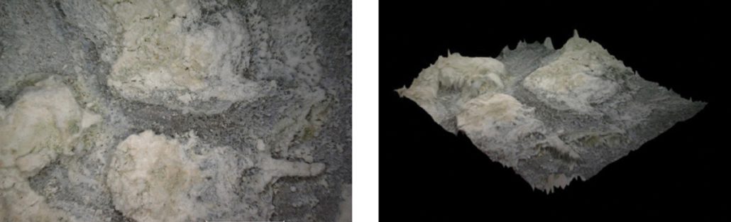
Figure 1. Two- and three-dimensional color images of an aluminum annode plate showing light-colored deposits that have caused uneven wastage. The 3D image shows the extent of material removal in locations where deposits are not present. Normal wastage in this application should be uniform.
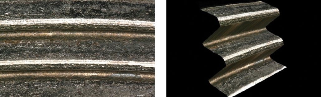
Figure 2. Two- and three-dimensional color images showing fastener thread flank damage and a crack origin near the root of the upper thread. The 3D image shows that the crack origin is located on the thread flank rather than at the deepest part of the thread root.
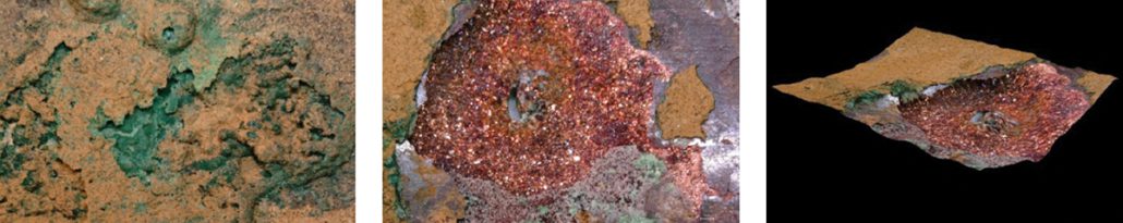
Figure 3. Two- and three-dimensional images of a copper heat exchanger tube that has been damaged from under-deposit corrosion (UDC). The image at left shows the typical appearance of the ID deposits. The center image shows a region of damage surrounding a pinhole leak. The 3D image provides an idea of the depth of internal corrosion in the tube.
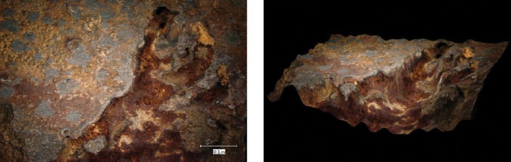
Figure 4. Two- and three-dimensional images of a region of damage on an internal surface of a feedwater pump. The image at left shows the appearance of brownish deposits found within the corroded region of the pump surface. The 3D image provides an indication of the depth and shape of the corrosion damaged region.
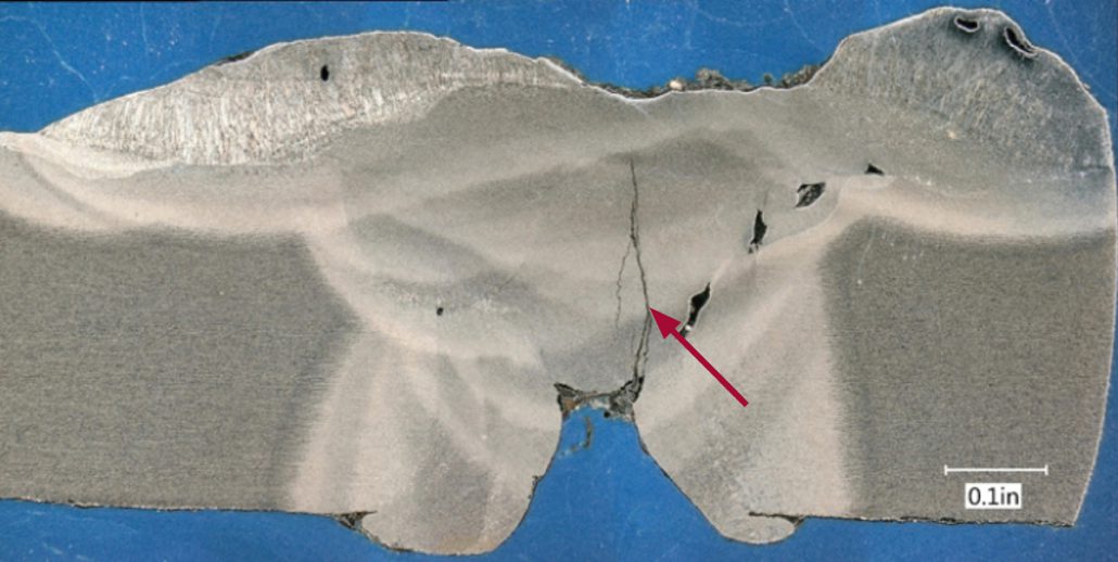
Figure 5. Two dimensional stitched image of a weld cross section showing cracking emanating from a shallow weld root. Porosity is also visible in multiple locations in the weld.
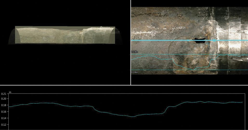
Figure 6. Images of a region of damage on the exterior of a heat exchanger tube where wastage has occurred near the tube sheet. The upper right image is a view of the leak location with an overlay of lines showing the position where the surface profile was documented as well as the depth profile (overlaid and in the lower image). The upper left image, which has an appearance similar to an x-ray, is a side view of the 3D image of the tube surface.