
Online Monitoring of HRSG with SIIQ™
A CASE STUDY ON IMPLEMENTATION AT A 3X1 COMBINED CYCLE FACILITY (ARTICLE 1 OF 3)

A CASE STUDY ON IMPLEMENTATION AT A 3X1 COMBINED CYCLE FACILITY (ARTICLE 1 OF 3)
High Energy Piping Monitoring SI moves beyond the pilot application of a High Energy Piping
By: Wendy Weiss Soot blower erosion (SBE) is caused by mechanical removal of tube material
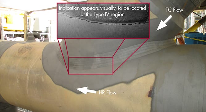
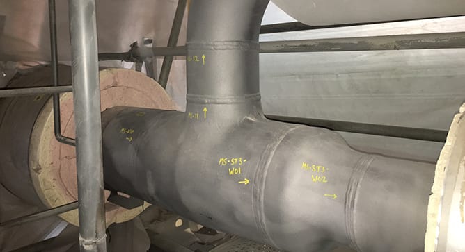
By: Ben Ruchte Fabricated branch connections represent a common industry issue in combined cycle plants.
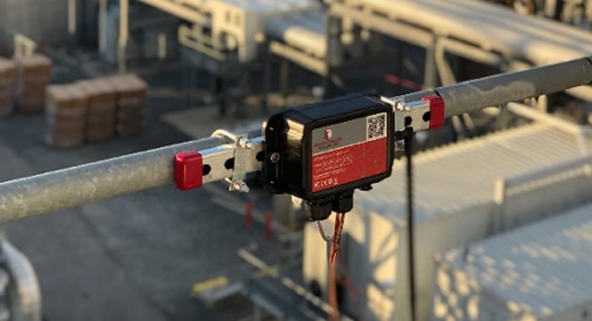
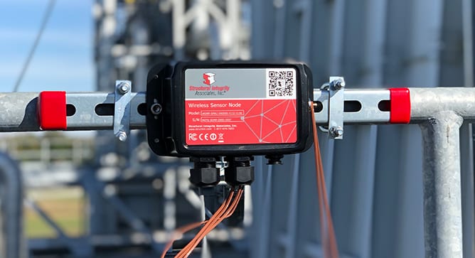
By: Jason Van Velsor, Matt Freeman and Ben Ruchte Installed sensors and continuous online monitoring
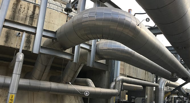
By: Ben Ruchte and Kane Riggenbach To provide operating flexibility, combined cycle plants are typically
By: Ben Ruchte, Steve Gressler, and Clark McDonald Properly inspecting plant piping and components for

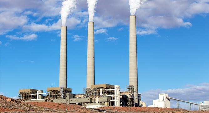
It is well known that conventional coal-fired utility boilers are cycling more today than they
By: Wendy Weiss Superheater/reheater fireside corrosion is also known as coal ash corrosion in coal
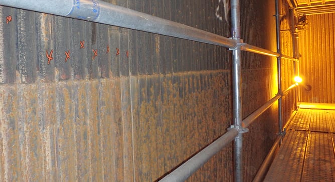
By: Wendy Weiss Industry experience shows that waterwall tubing in conventional boilers can be susceptible