News & Views, Volume 53 | Phased Array Ultrasonic Testing (PAUT) Monitoring with Ultrasonic Thick-Film Arrays

Traditional nondestructive examination (NDE) activities are planned based on hours of service, number of load cycles, time elapsed since previous inspections, or after the emergence of clear and obvious damage in a component. While engineering judgment and risk analysis can, and should, be used to prioritize inspections, these prioritizations are not based on the actual physical condition of the component or material it is constructed from but on precursory conditions that may or may not lead to eventual damage. Alternatively, continuous monitoring approaches can facilitate advanced planning and the optimization of Operations and Maintenance (O&M) spending by enabling the prioritization of inspections based on a component’s actual current condition. Furthermore, continuous monitoring enables earlier detection, which allows the extension of the component’s remaining useful life through modified operation. 

SI’s recent advances with thick-film are breakthrough technologies for long-term monitoring and imaging of crack growth in critical components.

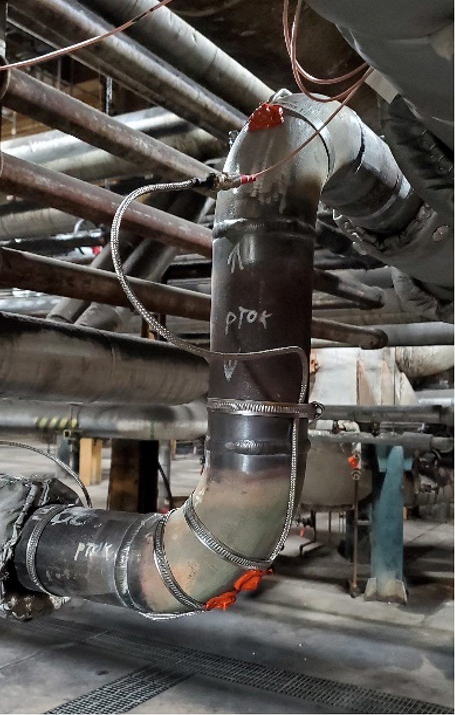
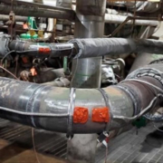
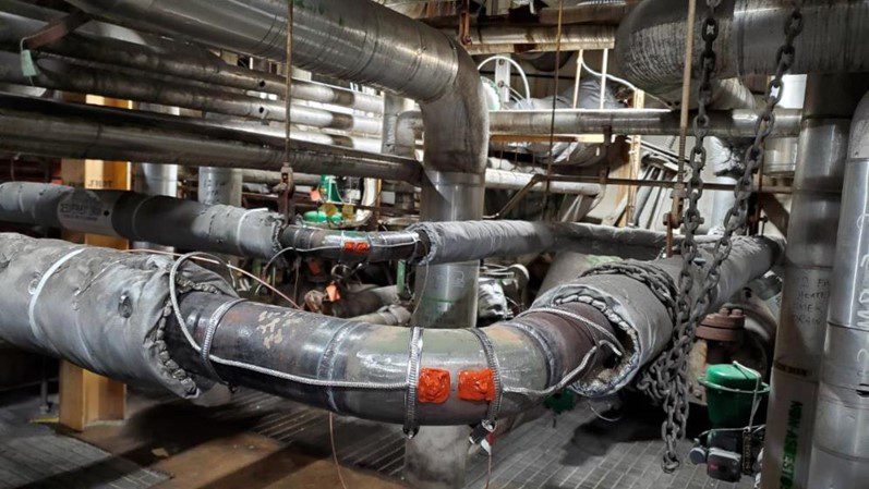
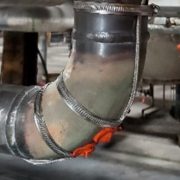
Figure 1. Installed thick-film UT sensors for thickness monitoring of elbows.

Given the trend of fewer on-site resources and tighter O&M budgets, the energy industry has a strong motivation to progress toward condition-based inspection and maintenance. To facilitate this evolution in asset management strategy, new monitoring sensor technologies are needed, ones that provide meaningful monitoring data directly correlated to the condition of the material or asset. To support this need Structural Integrity has developed a novel thick-film ultrasonic sensor solution. Initially developed for basic applications, such as thickness monitoring, SI’s recent advances with this technology make long-term monitoring and imaging of crack growth in critical components possible.

BACKGROUND
Ultrasonic thick-films are comprised of a piezoelectric ceramic coating that is deposited on the surface of the component that will be monitored. A conductive layer is then placed over the ceramic layer, and the ceramic layer deforms when an electric potential is applied across the film. When a sinusoidal excitation pulse in the ultrasonic frequency range is applied across the film, the vibration of the film is transferred into the test component as an ultrasonic stress wave.   

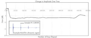
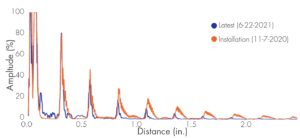
Structural Integrity initially developed our thick-film ultrasonic sensors for real-time thickness monitoring and has demonstrated the performance and longevity of this technology through laboratory testing and installation in industrial power plant environments, as seen in the photograph in Figure 1, where the sensors have been installed on multiple high-temperature piping components that are susceptible to wall thinning from erosion. In this application, the sensors are fabricated directly on the pipe’s external surface, covered with a protective coating, and then covered with the original piping insulation. Following installation, data can either be collected and transferred automatically using an installed data acquisition instrument, or a connection panel can be installed that permits users to acquire data periodically using a traditional off-the-shelf ultrasonic instrument. Example ultrasonic datasets are shown in Figure 2.

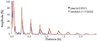
Figure 2. Ultrasonic datasets from an installed thick-film UT sensor at two different points in time.

TECHNOLOGY ADVANCEMENTS
Recently, SI has demonstrated the ability to create thick-film sensors with complex element arrays that can be individually controlled to steer and focus the sound field, as with traditional phased-array ultrasonic testing (PAUT). Moreover, data from individual array elements can be acquired and post-processed using full-matrix capture (FMC) techniques. FMC is a data acquisition technique where all elements in the array are used to both transmit and receive ultrasonic waves. The result is a large data matrix that can be used for further processing with various post-processing techniques. Compared to more traditional active focusing, FMC is well-suited for a fixed transducer array, as scanning speed is not a concern. Another advantage is that the electronics needed for data acquisition can be simplified – requiring only a single pulsing channel.

A thick-film Linear-Phased Array (LPA) installed on a standard calibration block is shown in Figure 3. The two images shown on the right were generated using the Total Focusing Method (TFM) post-processing algorithm, with the image on the far right having an adjusted color scale to highlight the imaging of the notches toward the bottom of the calibration block. TFM is an amplitude-based image reconstruction algorithm where the A-scans from the FMC dataset are used to synthetically focus on every point in a defined region of interest.

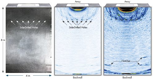
Figure 3. FMC TFM results from a thick-film linear phased array installed on a calibration block.

Using other information from the FMC dataset, such as the phase of the waveforms, has proven to be beneficial in certain cases. At each focal point in the region of interest, a large phase coherence among all the waveforms can be indicative of a focused reflector. This can then be applied to the TFM image at each focal point as a weighting factor (also known as the Phase Coherence Factor (PCF)) to improve the signal-to-noise ratio. 

Figures 4 and 5 illustrate the results of applying the phase coherence imaging technique to the FMC datasets collected with thick film transducer arrays. The sample is a section of high-energy piping approximately 1.7 inches thick with cracking at various positions along a girth weld. The sample has a counterbore with ID-initiated cracks up to approximately 0.5 inches in length coming from the taper of the counterbore. The thick film transducer arrays were located at different positions along the weld.

SUMMARY
The energy industry is moving away from traditional scheduled-based planning for inspection and maintenance activities and toward “smart plant” concepts that rely more heavily on data correlated to actual component conditions. To accomplish this, there is a need for new and novel monitoring technologies that are both unobtrusive and able to withstand the harsh conditions of industrial facilities. Collecting robust and meaningful monitoring data will be critical in ensuring that safety and asset reliability are maintained and even improved. Structural Integrity’s thick-film UT technology has been developed to achieve this goal and continues to evolve for higher-temperature components and more advanced applications. We are ready to support a variety of in-field applications, contact one of SI’s experts if you have questions or a potential application that could benefit from installed thick-film UT sensors.

Figure 4. Phase coherence imaging result from a thick film transducer array on a cracked weld sample.

Figure 5. Phase coherence imaging result from a thick film transducer array on a cracked weld sample.

News & Views, Volume 51 | Drone Inspections

SI EXPANDED CAPABILITIES

By:  Jason Van Velsor and Robert Chambers

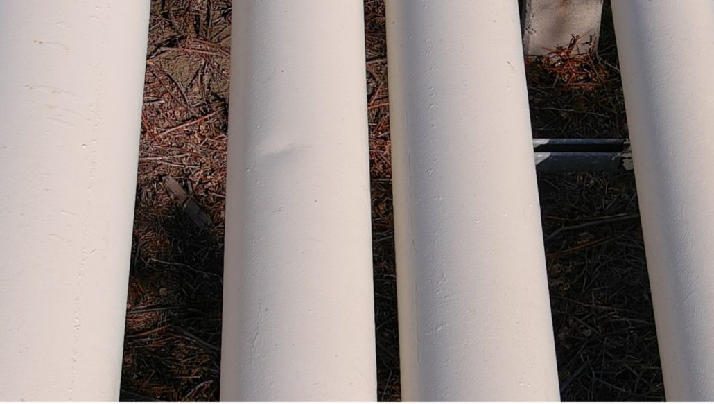
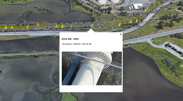
Structural Integrity (SI) has recently added drones to our toolbox of inspection equipment. Using drones, inspectors are able to complete visual inspections safely and more efficiently. Applications of drones for visual inspections include plant and piping walkdowns, structural inspections and atmospheric corrosion monitoring (ACM) of exposed pipeline.

Figure 1. Drone image of a dent on an elevated section of pipeline

Pipe hanger walkdowns at fossil and combined cycle plants are part of a routine inspection process. During these inspections, the inspector is required to view and mark down pipe hanger positions and assess their condition. While some hangers provide easy access for the inspector, this is not always the case. Some of these may be located in elevated positions that require the plant to build out scaffolding, which not only increases the cost, but also can put the inspector at risk when working at elevation. With the use of drones, the inspector can fly up to the pipe hangers from a safe location and get a live high-resolution video feed from the camera mounted on the drone. Saving pictures and the video footage can also allow the inspector to go back and review the footage at a later time.

ACM is another example where drones have proven to be a useful tool. ACM inspections of outdoor above ground pipelines are typically done by

walking down the pipeline and recording any signs of atmospheric corrosion. There are many occasions where the pipeline will be elevated or cross over rivers and railroads, requiring scaffolding or fall protection. By using a drone to fly along the pipeline, the inspection can be completed much more efficiently and safely. In situations where a GPS signal is available, such as outdoor pipeline inspections, the GPS coordinates can be saved with each photo. Custom SI-developed software can then automatically compile the acquired images and create a KML file to be viewed in Google Earth, allowing the client to get an overview of the inspection results. 

Figure 2. Google Earth view of image locations

Moving forward, SI plans to utilize these drones for more than just visual inspections. Possible applications could include using drones to perform ultrasonic thickness testing or Structural Integrity Pulsed Eddy Current (SIPEC™) examinations. All of SI’s pilots in command hold valid FAA Part 107 certificates and pilot registered drones.

Get News & Views, Volume 51

Structural Integrity Associates | News and Views, Volume 51 | High Temperature Ultrasonic Thickness Monitoring

News & Views, Volume 51 | High Temperature Ultrasonic Thickness Monitoring

TECHNOLOGY INNOVATION – THICK FILM SENSORS

By:  Jason Van Velsor and Robert Chambers

Figure 1 – Photograph of an ultrasonic thick-film array for monitoring wall-thickness over a critical area of a component.

The ability to continuously monitor component thickness at high temperatures has many benefits in the power generation industry, as well as many other industries. Most significantly, it enables condition-based inspection and maintenance, as opposed to schedule-based, which assists plant management optimizing operations and maintenance budgets and streamlining outage schedules. Furthermore, it can assist with the early identification of potential issues, which may be used to further optimize plant operations and provides ample time for contingency and repair planning.

Over the last several years, Structural Integrity has been working on the development of a real-time thickness monitoring technology that utilizes robust, unobtrusive, ultrasonic thick-film sensor technology that is enabling continuous operation at temperatures up to 800°F. Figure 1 shows a photograph of an installed ultrasonic thick-film array, illustrating the low-profile, surface-conforming nature of the sensor technology. The current version of this sensor technology has been demonstrated to operate continuously for over two years at temperatures up to 800°F, as seen in the plot in Figure 2. These sensors are now offered as part of SI’s SIIQ™ intelligent monitoring system.


ultrasonic signal amplitude

Figure 2 – A plot of ultrasonic signal amplitude over time for a sensor operating continuously at an atmospheric and component temperature of 800°F.

In addition to significant laboratory testing, the installation, performance, and longevity of Structural Integrity’s thick-film ultrasonic sensor technology has been demonstrated in actual operating power plant conditions, as seen in the photograph in Figure 3, where the sensors have been installed on multiple high-temperature piping components that are susceptible to wall thinning from erosion. In this application, the sensors are fabricated directly on the external surface of the pipe, covered with a protective coating, and then covered with the original piping insulation. Following installation, data can either be collected and transferred automatically using an installed data acquisition instrument, or a connection panel can be installed that permits users to periodically acquire data using a traditional off-the-shelf ultrasonic instrument.

Figure 4 shows two sets of ultrasonic data that were acquired approximately eight months apart at an operating power plant. The first data set was acquired at the time of sensor installation and the second data set was acquired after approximately eight months of typical cycling, with temperatures reaching up to ~500°F. Based on the observed change in the time-of-flight between the multiple backwall echoes observed in the signals, it is possible to determine that there has been approximately 0.005 inches of wall loss over the 8-month period. Accurately quantifying such as small loss in wall thickness can often provide meaningful insight into plant operations and processes, can provide an early indication of possible issues, and is only possible when using installed sensors.

Other potential applications of Structural Integrity’s ultrasonic thick-film sensor technology include the following:

  • Real-time thickness monitoring
    • Flow Accelerated Corrosion (FAC)
    • Erosion / Corrosion
  • Crack Monitoring
    • Real-time PAUT
    • Full Matrix Capture
    • Critical Area Monitoring
  • Other Applications
    • Bolt Monitoring
    • Guided Wave Monitoring

In addition to novel sensor technologies to generate data, Structural Integrity offers customizable asset integrity management solutions, as part of the SIIQ platform, such as PlantTrackª, for storing and managing critical data. Many of these solutions are able to connect with plant historians to gather additional data that feed our engineering-based analytical algorithms, which assist in converting data into actionable information regarding plant assets. These algorithms are based on decades of engineering consulting and assessment experience in the power generation industry.

Reach out to one of our NDE experts to learn more about SI’s cutting-edge thick-film UT technology.

Figure 3 – Photograph showing Structural Integrity’s thick-film ultrasonic sensor technology installed on two high-temperature piping elbows that are susceptible to thinning from erosion.


Ultrasonic waveforms acquired approximately 8 months

Figure 4 – Ultrasonic waveforms acquired approximately 8 months apart showing 0.005 inches of wall loss at the sensor location over this period.


Get News & Views, Volume 51

News & View, Volume 48 | SI Field Service Quality and Efficiency Solutions

News & Views, Volume 48 | SI Field Service Quality and Efficiency Solutions

By:  Robert Chambers and Trey RippyNews & View, Volume 48 | SI Field Service Quality and Efficiency Solutions

To help meet demanding outage schedules and stay within lean operation and maintenance budgets, Structural Integrity Associates, Inc. (SI) has implemented several new field data collection and analysis tools that enable delivery of a higher-quality final inspection product in a more efficient manner. These include customized software tools for streamlining the NDE data acquisition, analysis, and reporting processes. Moving forward, these tools will reduce time-on-pipe for inspections, as well as the associated analysis and reporting time.

For large inspection scopes, collecting, tagging, managing, transferring, and documenting data can be a very labor-intensive process with opportunities for human performance errors. While inspection instruments and analysis software typically have built-in reporting capabilities, these tend to be very general so they can be applied to a wide variety of applications. This can make it cumbersome to tailor these features to a specific application.

READ MORE