News and Views, Volume 55 | 
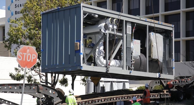
Replacement of Large Equipment in Nuclear Power Plants

By:  Julio Garcia, PhD, PE, Natalie Doulgerakis, PE, SE, Dan Parker, PE and Lachezar Handzhiyski

With many U.S. nuclear plants having extended operation well beyond their original licensed life, it is necessary to replace certain critical process components (e.g., large pumps, turbine rotors, heat exchangers). In many cases, equipment manufacturers are asked to provide larger, heavier equipment to deliver higher output and improve efficiency. Prior to installation, the existing structure must be evaluated for the larger static loads as well as one-time loads applied during movement (transit and rigging). SI has successfully collaborated with owners, design engineers, equipment manufacturers, and installation contractors to ensure safety and minimize disruption during this process.

The U.S. power grid continues to benefit from the extended operation of traditional nuclear power plants, most of which began operation between 40 and 55 years ago. Due to unprecedented market demand, many plant owners are actively pursuing extended operating licenses (subsequent license renewal or SLR), and increased thermal and electrical power output (extended power uprate or EPU). Whether due to normal aging or increased performance demands, many plants are facing the challenge of replacing large pieces of original equipment (e.g., pumps, turbine rotors, heat exchangers) embedded deep within the facility. In many cases, sites are requiring larger and heavier replacement equipment to provide improved efficiency or additional margin.

THE CHALLENGE

Frequently, the initial structural design of these facilities typically did not explicitly account for replacement of certain large equipment (e.g., feedwater heaters, moisture separators, etc.). The removal, hauling, sliding, jacking, and installation of replacement equipment are new tasks that introduce significant operational and structural demands on the building structures as well as challenges to plant staff. High-demand loads may be temporarily imparted to building structures that were optimized during their original design based on original equipment and operations loads with limited strength margins. Re-evaluation of the building structure under the new, larger service loads is required, typically including gravity, seismic, wind, piping, and thermal loads.  Particularly challenging and sometimes overlooked are new thermal loads imposed on the gravity load-resisting system of the building. These loads are the result of thermal deformations within the equipment piece itself or within other mechanical attachments, such as piping system that connects to it. Rigorous analyses are performed where there are complex networks of such attachments. Where multiple attachments connect to an equipment piece, it is key to combine the loadings at each attachment location in a conservative, yet realistic manner, to safely demonstrate structural adequacy.

SI has a proven track record of overcoming these challenges by applying rigorous structural analysis, optimizing retrofit strategies, and leveraging multi-disciplinary collaboration to limit disruption and minimize costs.

SI’S ROLE

Structural Integrity (SI) has provided key consulting services to support the replacement of large equipment for SLR and EPU, including moisture separator reheaters (MSRs) and feedwater heat exchangers (FWHs), among others. Working both as task leads, as well as independent reviewers, SI staff have successfully collaborated with owners, design engineers, equipment manufacturers, and installation contractors to safely replace large equipment. SI has provided key consulting related to technical and operational issues, helping to minimize disruption. Additionally, SI has provided a holistic approach that considers the benefits and challenges associated with use of different standards and methodologies to assess and potentially retrofit building structures designed and licensed many decades ago. As a result, SI structural engineers have been praised for providing significant contributions to optimize the process and minimize costs.

Figure 1. Operating Deck of a turbine building.

KEY SOFTWARE FOR STRUCTURAL ASSESSMENTS

Used for structural analysis and design, GTSTRUDL helps evaluate framing systems and load distribution under gravity, seismic, and equipment-induced forces.

A general-purpose structural analysis tool, SAP2000 assesses floor framing response to new equipment loads, ensuring existing structures can accommodate changes safely.

A high-fidelity FEA tool, ABAQUS models localized stress, thermal effects, and nonlinear interactions, providing detailed results in highly-stressed regions to maximize available structural margins.

PIPING ANALYSIS

Used to evaluate thermal, pressure, and mechanical loads applied to large stationary components, piping analysis software ensures system integrity and compliance with applicable codes (e.g., ASME B31.1). SI utilizes PIPESTRESS, AutoPIPE, and CEASAR II for these evaluations, depending on application needs and/or designer preferences.

PROJECT EXAMPLE 1 (1,158 MW 4-Loop PWR)

In support of the planned MSR replacement, SI developed 3-dimensional finite element models of the MSR units and their support frames, as well as the framing at the operating floor of the turbine building.

  • Assessed combinations of pipe dead and thermal loads acting at MSR nozzle attachment locations to determine the most critical loading condition on the support frames and floor framing.
  • Performed stress analysis of support frames to evaluate structural elements, welds, and bolted connections using ABAQUS.
  • Performed structural evaluation of floor framing using SAP2000.
  • Calculated framing member and connection capacities using the provisions of AISC 360 and ACI 318.

SI evaluated all structural elements within the MSR load path and confirmed the structure’s adequacy to resist the demands given the design loads provided by the plant staff. The result: SI’s recommendations and selected approach led to no structural retrofits being required of the turbine building, thus ensuring the planned operation was safe to perform while saving the unnecessary expense of reinforcing the structure.

PROJECT EXAMPLE 2 (1,220 MW 4-Loop PWR)

SI acted as the Owner’s engineer and performed an independent review of the MSR replacement project, including a review of the structural analysis of the turbine building under the installation and operation of the new and heavier MSRs, as well as the proposed structural retrofits.

  • Independent review of the turbine building analysis methodology and numerical model in GTSTRUDL software.
  • Review of loading and requirements data from design basis criteria, calculations, licensing commitments, manufacturer information and transport/hauling information.
  • Verification of loading data in GTSTUDL model.
  • Assessment of structural member capacity results from GTSTRUDL model.
  • Performance of independent calculations for steel-reinforced concrete composite section capacities.
  • Provided recommendations on the analysis methodology, loading data and applicable design standards to optimize the strength margins of the existing turbine building.

Through an independent review of the MSR replacement project, SI demonstrated unrealized structural margin, reduced the number of structural retrofits to support the heavier MSR units, and provided recommendations on licensing strategy for the review and approval of the structural modifications supporting the MSRs replacement.

Figure 2. Sliding and Replacement of a Moisture Separator Reheater.

Download Volume 55

News & Views, Volume 49 | Code Compliance and the Modular Construction Trend: What Manufacturers Need to Know to Comply with Building Codes

By:  Andy Coughlin, PE, SE

News & Views, Volume 49 | Code Compliance and the Modular Construction Trend

The modular construction industry is projected to grow globally at an annual rate of 6.9%, outpacing the growth of traditional construction.1  Modular construction has many advantages over traditional building methods, including improved quality control and shorter project durations. Factory-built systems are constructed in controlled environments with equipment and materials that are not feasible at congested job sites, and project schedules can be shortened when factory work and field work are performed in parallel.

However, modular projects may stumble without proper forethought: when fabrication takes place in a factory away from the jobsite, the building officials, inspectors, and engineers can have less oversight and less recourse to implement changes if issues are discovered in the field.  Code compliance may also be an issue when systems are designed by factory engineers rather than the engineer of record.  To mitigate these potential pitfalls, careful planning is required at the start of the project.

MORE

News & Views, Volume 49 | The 4th Dimension: Lifecycle Assessment of Critical Structures

By:  Dan Parker, PE

News & Views, Volume 49 | The 4th Dimension- Lifecycle Assessment of Critical Structures

By analytically simulating the steps in the construction process, including the sequence of concrete placements, and tracking the history of the material behavior starting from initial placement, the potential for cracking is evaluated by comparing the time dependent stress and strains to the concrete cracking resistance and capacity.

Aging Infrastructure Issues

The infrastructure in the United States is aging and, whether publicly or privately owned, significant resources are required to repair, replace, or modernize it.  Due to the high costs associated with these efforts, owners need to identify structures with high risk-of-failure consequences and find the most cost-effective solutions for rehabilitation.  High consequence infrastructure includes:

  • Highway and railway bridges,
  • Roadways for intra and interstate transportation,
  • Dams, locks, and levees for flood control and cargo transportation,
  • High rise business, apartment, and condominium towers, and
  • Power generation and distribution facilities for Nuclear, Fossil and Hydro utilities.

All infrastructure, is susceptible to degradation that comes with aging.  The accumulation of degradation, and a structures subsequent failure, is difficult to predict due to the numerous real-world factors that influence rates of degradation.  These real-world factors can lead to some structures failing prematurely and others lasting well beyond their original design life.  Asset owners need to be on the lookout for:

  • A structure that is nearing or has exceeded its expected design life,
  • A structure that shows signs of steel corrosion, freeze-thaw damage, or concrete degradation such as alkali aggregate reaction (AAR),
  • A structure that is overloaded due to an increase in auto, truck or rail traffic,
  • A structure with a known design deficiency when evaluated with modern design code requirements,
  • Increases in regional hazards, such as increased seismicity or increased probable maximum flood levels, and other climate change related issues.

Often, structures are kept in service beyond their original design life.  Many older structures are held to a design basis, i.e. code requirements, consistent with the time the structure was designed. Evaluating older structures using current code requirements can potentially affect original safety margins both positively and negatively. Increased capacity limits can be established for steel welded and bolted connections and utilizing actual concrete compressive strengths above original design strength that may provide added safety margin. On the other hand, identifying substandard details relative to current practice, particularly concrete reinforcement detailing will reduce originally considered safety margins. Additional factors that can affect the service life of a large infrastructure projects include environmental conditions, reliability of materials, quality of construction, and loading conditions.

Throughout the country, many structures such as bridges, dams, and power generating facilities remain in active service as they approach or exceed their design (or licensed) service life. Replacement is often prohibitive for many of these structures due to cost. However, failure of these structures could have more significant consequences beyond lost revenue, including loss of life.  Identifying structural vulnerabilities and designing retrofit modifications is essential to economically extending the service life of these structures.

Current Regulations

There is no single agency that oversees the various types of infrastructure within the United States. The following structures generally fall under the purview of these agencies:

  • Bridges, Roadways and Railways – National Transportation Safety Board, Federal Highway Administration, State Level Departments of Transportation, and some local City Departments of Transportation
  • Nuclear Facilities – Nuclear Regulatory Commission (NRC), US Department of Energy
  • High Rise Buildings – State and Local City Building Departments
  • Dams for Hydroelectric and Water Storage – Federal Energy Regulatory Commission (FERC), State Level Dam Safety Departments
  • At a high level the different regulatory bodies have a common mission to keep asset owners accountable to maintaining the mandated level of safety for the general public. Different regulations and procedures are required depending on the type of project, owner, and overseeing agency involved.

Lifecycle of a Structure

As structures reach the end of their design service lives or are in extended service, regulators typically require asset owners to demonstrate that these structures can still maintain their functionality while posing a low risk to the public safety, regardless of expense to the owner. Thus, it is beneficial for the owner to perform maintenance to ensure safe and functional assets that are profit positive, versus the potentially large costs incurred during decommissioning, removal and remediation of project sites.

Lifecycle structural health monitoring and simulation is a methodology to track changes in a structure that occur during the structures service life. Monitoring can be performed through non-destructive examination techniques. Continuous health monitoring helps owners maintain their assets by providing a warning if a sudden change or degradation accumulation is observed.  This data can feed desktop simulations which incorporate the time variable into the modeling of the asset, giving point-in-time snapshots of how the structure behaves under loading during different stages of its life.

Predicting Degradation: During Design

During the design phase, large infrastructure projects are designed for a variety of expected loads including thermal load cycles, live loads,  and operational loads. Seldom is the cumulative impact of cyclic loading considered when estimating the expected service life of the structure. Incorporating transient seismic demands or some other unexpected blast, shock or impact loading in combination with the expected stress range that occurs in structural components the lifecycle endurance limit can be evaluated that may be different from originally established design basis limits. For example, concrete degradation typically manifests itself as cracking, sometimes occurring in unexpected locations. Cracking can allow water infiltration, leading to internal corrosion of reinforcement and corrosive swelling, which can weaken the structure and accelerate degradation. In cold environments repeated freeze-thaw cycles will further damage the concrete. 

Cumulative damage not only affects the loss of static strength, but will also change the dynamic characteristics of the structure. This can lead to the poor performance of a structure supporting vibrating equipment or a structure subjected to seismic loading. By incorporating the effects of damage accumulation in a structural assessment, the time-varying dynamic characteristics of the structure can be identified. Incorporating these effects as part of a lifecycle assessment can provide the owner with a more realistic understanding of actual structural condition of their asset that can guide targeted remediations (i.e. mitigate excess equipment vibration) or alert the owner to an increased risk of failure under a postulated seismic event.  

Predicting Degradation: During Construction

During construction of mass concrete structures large temperatures develop due to concrete curing.  A Nonlinear Incremental Segmental Analysis (NISA) evaluates the thermal and static loading of young concrete to determine the potential for cracking.  The propensity for cracking depends on the concrete mix, environment, and boundary conditions imposed during construction.  The concrete temperature varies with time and depends on the volume and rate of concrete placement, the sequence and geometry of the placements, the concrete placement temperature and heat generation rate, and the ambient conditions.  The boundary conditions imposed during construction depend on the sequence and geometry of the placements, the interaction with the foundation/formwork and any adjacent or embedded structures, and the time dependent aging, creep, and shrinkage properties of the already placed concrete lifts.  To accurately account for all of these factors, the NISA must be capable of representing a coupled thermal-mechanical analysis with nonlinear material properties.  By analytically simulating the steps in the construction process, including the sequence of concrete placements, and tracking the history of the material behavior starting from initial placement, the potential for cracking is evaluated by comparing the time dependent stress and strains to the concrete cracking resistance and capacity.  The cracking resistance is constant for any mature concrete present, such as pre-cast concrete forms, but is time dependent for the freshly placed young concrete since the tensile strength and modulus are changing as the concrete hardens and ages.

Figure 1. Aging Structures and Decreasing Margin of Safety

Predicting Degradation: During Service

A concrete structure often has predictable and repeating loading patterns over the course of its service life.  For instance, a dam will reliably have high and low water levels throughout the year, though the actual levels may depend on the weather in a given year.  A bridge will reliably experience different load patterns in weekday versus weekend traffic.  A nuclear containment structure will experience thermal load cycles during power generation operation and shutdown for planned outages.  

When looking into the future, engineers make reasonable predictions of different loading events during the initial design phase of a structure. Supplementing these prediction methods with sensor data and observed damage from onsite can help predict the time where the structure goes from safe to unsafe and remedial measures need to be taken. Sophisticated concrete material models, such as SI’s proprietary ANACAP model, can incorporate all known forms of time-based concrete behavior such as creep, shrinkage, radiological degradation, cement hydration, alkali aggregate reaction, steel corrosion, scour of concrete, and freeze-thaw cycles. This can further enhance the predicted structural performance during the design basis and extended license period of critical infrastructure as part of an asset owners risk management program.

Figure 2. Concrete arch dam circa 1909, aging degradation Issues subject to increased flood and seismic demands

Time-Dependent Margin

Figure 1 shows the capacity of a structure to resist a large event (such as a flood or earthquake), and how the margin of safety changes over time. Due to safety factors built into design codes, new structures have a minimum margin of safety against failure even when accounting for small design approximations and construction errors.  That margin of safety can decrease when a transient event causes damage (e.g. an earthquake, ship impact, or large flood) and as the structure ages and degrades over time.  Further reductions in margin can occur as hazards can increase over time, such as when flood events become more common or when new earthquake faults are discovered from geologic mapping.  Over a structure’s service life, as it accumulates damage from both transient events and aging, the available margin may be much lower than what was originally intended, increasing the risk of catastrophic failure.

Figure 3. Concrete placement with active cooling to reduce concrete heat generation

Answering Tough Questions

Can an asset survive an earthquake or large flood event today? How big of an event can it survive? Can it survive the same event ten years from now?  How does the structural performance change if we put a remedial measure into place?  Without remediation, how long until the structure is unsafe? These questions can be answered with time-based structural lifecycle modeling.  

Although much of the infrastructure in the USA is already functionally obsolete – or worse: at risk of catastrophic failure – much of it is effectively operating safely beyond its original design life.  Finding assets with the highest risk allows owners to prioritize limited funding for rehabilitation and remediation.  Lifecycle modeling helps answer those important questions when the key decisions need to be made.

Figure 4. Example of Section Loss Contour using High Definition Scanning (HDS), Spectral Analysis of Surface Waves (SASW) and Acoustic Tomography (AT) Methods


Get News & Views, Volume 49

News & Views, Volume 47 | Aircraft Impact Assessments for NUSCALE Power

By:  Eric Kjolsing, Ph.D., PE

From 2015 to 2019 Structural Integrity Associates, Inc. (SI) worked with News & View, Volume 47 | Aircraft Impact Assessments for NUSCALE PowerNuScale Power,LLC. to develop structural details for and perform aircraft impact assessments of NuScale’s SMR Reactor Building.  The assessments were based on finite element analyses of various strike scenarios stemming from NEI 07-13 guidance.  ANACAP, a proprietary SI concrete constitutive model, was used in the finite element analyses.  Among other capabilities, the ANACAP model can capture multi-axial tensile cracking, compressive crushing with strain softening, and crack dependent shear stiffness.

READ MORE

News & Views, Volume 46 | Adding Value Through Test Informed Modeling: Hydro Structures

By: Eric Kjolsing and Dan Parker

News & View, Volume 46 | Adding Value Through Test Informed Modeling- Hydro StructuresIn 2018, Structural Integrity Associates (SI) supported a utility in the structural assessment of a submerged concrete intake tower.  The tower is nearly a century old and was investigated as part of the utility’s periodic maintenance program. 

The assessment required the generation of an analysis model that accounted for both the structure and the surrounding water.  When accounting for fluid effects, a typical analysis approach is to develop a fluid-structure interaction (FSI) model that explicitly accounts for the interaction between the surrounding water and concrete tower.  However, this modeling approach is expensive both in terms of (a) cost, due to the increased effort needed in generating the model and (b) schedule, due to the increased analysis run time.  In lieu of developing an FSI model, SI implemented an alternative numerical approach to model the effects of the water and justified the approach through physical testing of the in-situ structure.

READ MORE

News & Views, Volume 45 | Improved Asset Management Through Test Informed Analysis

News & View, Volume 45 | Improved Asset Management Through Test Informed AnalysisBy:  Eri Kjolsing

Introduction
Structures may experience unforeseen operating environments or site-specific hazards leading to changes in the structure’s performance, safety, and longevity.  These changes often prompt asset owners to undertake analysis efforts to ensure satisfactory structural performance for the updated conditions. However, conventional analyses that fail to capture the true behavior of a structure can lead to inaccurate analysis results, causing owners to make less than ideal asset management decisions.  Structural Integrity (SI) is uniquely positioned to pair our dynamic characterization and advanced structural analysis capabilities to generate a better structural model.  SI vibration experts use impact testing, forced vibration, or ambient excitation sources, along with proprietary signal processing software, to non-destructively characterize the dynamic behavior of structural systems.  This characterization is used to inform advanced structural analyses by SI analysis experts to provide more accurate results related to operational improvements, damage location, and retrofits.

READ MORE

News & Views, Volume 44 | The Impact of the ASCE 7-16 Standard on Seismic Design and Certification of Equipment

By:  Matt Tobolski

News & View, Volume 44 | The Impact of the ASCE 7-16 Standard on Seismic Design and Certification of EquipmentThings change, that’s just a fact of life. But when it comes to engineering codes and standards, change can be confusing, frustrating and expensive. As it relates to seismic design and certification of equipment, it is beneficial to understand the impact of code changes early to begin incorporating requirements in new equipment design, product updates and in the certification process.

One of the main structural design codes used in the United States and abroad, American Society of Civil Engineering (ASCE) 7, undergoes revisions on a five-year cycle. These revisions are based on input from committee members, building officials, interested parties and academia with the goal of ensuring specific performance objectives are achieved as well as incorporating lessons learned from practice. With the increase in enforcement of seismic certification provisions over the past 10 years, there has been a noticeable increase in industry lessons learned. The updates to the seismic provisions in ASCE 7-16 relating to equipment design and certification can primarily be attributed to these lessons learned.

READ MORE

News & Views, Volume 43 | Advanced Structural Analysis

By:  Eric Kjolsing & Philip Voegtle

News & View, Volume 43 | Advanced Structural AnalysisThe sophistication of structural analysis has evolved side-by-side with computing and graphics technology.  Structural engineers have at their fingertips very powerful software analysis tools that assist them in evaluating very large and complex structures for stability, suitability, and code adequacy.  The tools themselves vary in complexity in proportion with the engineering analysis required of them – the most complex and unique engineering problems requiring the most advanced analysis tools. Structural Integrity is a leader in advanced structural analysis (ASA), utilizing state-of-the-art software and material science expertise to solve an array of structural and mechanical problems. 

Structural analysis, in its most basic definition, is the prediction of the structural performance of a given structure, system, or component to prescribed loads, displacements, and changes in temperature.  Common performance characteristics include material stresses, strains, forces, moments, displacements and support reactions.  The results from a structural analysis are typically compared to acceptable values found in design codes.  Meeting the design code acceptance criteria ensures a design that protects the public’s health, safety, and welfare.

ASA extends this basic definition of structural analysis to one-of-a-kind problems where the acceptance criteria may not be well defined.  Since loads, material behavior, or the structure itself can go beyond the scope of basic design codes, ASA requires an in-depth understanding of modeling techniques, software limitations, and non-linear material behavior.  In ASA, sophisticated finite element analysis solvers are utilized to gain a detailed understanding of a system’s non-linear mechanical behavior, providing a full three-dimensional view of the critical stresses and strains in a loaded system.

READ MORE