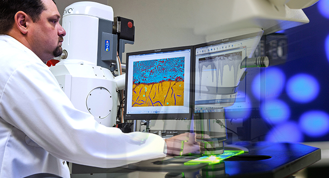
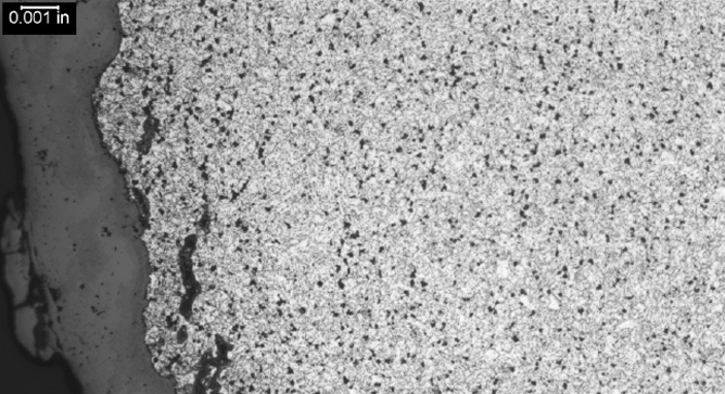
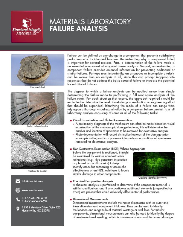
Materials Laboratory Failure Analysis
Failure can be defined as any change in a component that prevents satisfactory performance of

Failure can be defined as any change in a component that prevents satisfactory performance of
CREEP FATIGUE IN STEAM COOLED BOILER AND HRSG TUBES By: Wendy Weiss Creep-fatigue is caused
Strain-Induced Precipitation Hardening, also known as SIPH, is a commonly misinterpreted boiler tube failure mechanism
CIRCUMFERENTIAL THERMAL FATIGUE IN CONVENTIONAL WATERWALL TUBES By: Wendy Weiss Circumferential Thermal Fatigue damage in
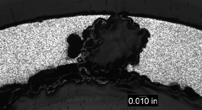
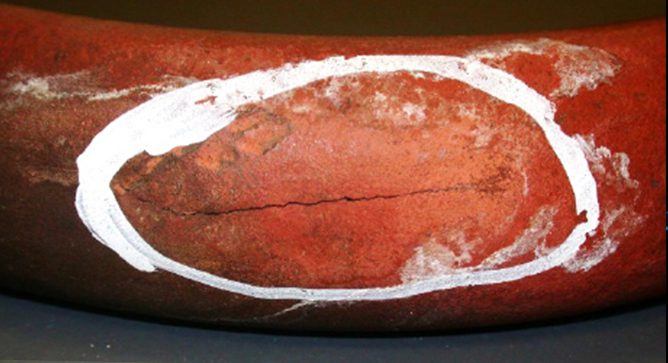
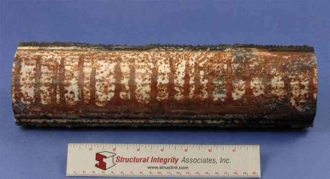
PITTING CORROSION IN CONVENTIONAL FOSSIL BOILERS AND COMBINED CYCLE/HRSGS By: Wendy Weiss Pitting is a
MATERIALS LABORATORY CASE STUDY 6 THE PROBLEM A supplier of electromagnetic interference (EMI) components noticed