CIRCUMFERENTIAL THERMAL FATIGUE IN CONVENTIONAL WATERWALL TUBES
By: Wendy Weiss
Circumferential Thermal Fatigue damage in Conventional Waterwall Tubes most commonly appears as circumferentially oriented cracking in the waterwalls of coal-fired supercritical units. Initially, the formation of ripple magnetite was a significant factor in the formation of this damage. Later, the introduction of oxygenated treatment controlled the formation of ripple magnetite, thus greatly reducing this damage mechanism.In the early 2000s, however, this type of thermal fatigue began occurring more frequently as low NOx burners and separated overfire air systems were introduced.
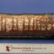
Figure 1. Tube with a series of circumferential cracks
Mechanism
Three basic factors contribute to this type of thermal fatigue damage.
The first factor is the starting tube temperature (i.e., the temperature under normal operating conditions). The higher the starting temperature, the greater the accumulation of damage in the affected tubing. For example, tubes subjected to higher heat flux or tubes with thick weld overlays will have higher average metal temperatures and accumulate damage more quickly.
The second factor is the extent of gradually increasing tube temperature caused by reasons such as internal deposit buildup, flame impingement, or unstable flow.
The third factor is the contribution of thermal transients due to slag shedding or using sootblowers or water cannons.
Essentially, the thermal fatigue cracking results from the combination of increasing tube metal temperature and thermal transients and is aggravated by high starting tube temperatures.
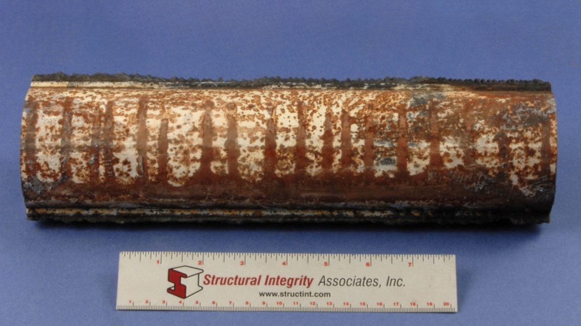
Figure 2. The external surface of the tube after the external deposits were removed
TYPICAL LOCATIONS
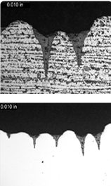
Figure 3. Cross-sectional views of the cracking in the etched (Top) and unetched (BOTTOM) conditions
Tubes with slag buildup and shedding
Areas affected by wall blow quenching
High heat flux locations
Areas affected by flame impingement
Cracking can be localized or widespread
Tends to be contained within a relatively narrow range of elevations
FEATURES
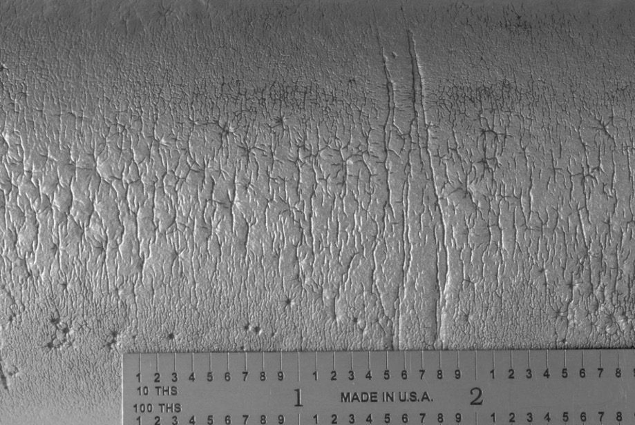
Circumferentially oriented, multiple, parallel cracks along the hot side of the tubes.
Notch shaped, oxide filled cracks in cross-section.
Adjacent tubes can exhibit variability in crack density.
ROOT CAUSES
High Initial Waterwall Tube Temperatures
Thick weld overlays
Higher heat flux
Flame impingement
Increasing Waterwall Tube Temperatures
Internal deposits including ripple magnetite, thick oxide layers, or feedwater corrosion products
Reduced internal flow rate
Formation of external oxides and deposits
Severe Thermal Transients
Natural or forced slag removal, including slag shedding and sootblowing
Use of water cannons or improper sootblowing
Flame instabilities
Unit operation, including forced fan cooling, rapid startups, frequent load cycling
Structural Integrity Associates, Inc. (SIA) is pleased to announce the appointment of Michael Battaglia as Vice President, Nuclear and Chief Nuclear Officer. Mr. Battaglia has served the prior three years leading the Project Management Office and Nuclear Business Development areas at SIA. During his 25-year career in the nuclear industry, Mr. Battaglia has held a variety of leadership roles that span operations and business development. Of Mr. Battaglia’s many operational accomplishments, building and leading the Westinghouse Balance of Plant Engineering Department, and leading the commercial deployment of a new alloy 600 mitigation technology in the US., are exemplary. In addition to his operational experience, Mr. Battaglia’s business development expertise has consistently enhanced the position of the business in the markets he has served.
Mark W. Marano, President and CEO of SIA, commented, “Mike’s blend of operational and business development backgrounds will bring a holistic approach to the implementation of the long-term strategic vision for SIA’s Nuclear business. His reputation of being highly engaged, not only with clients but with the entire staff at SIA, cements my confidence that this transition will go smoothly and pave the way for growth.”
Mr. Battaglia holds a B.S. in Industrial Engineering and an MBA from the University of Pittsburgh.
https://www.structint.com/wp-content/uploads/2023/09/Mike-Battaglia-News.jpg363668Structural Integrityhttps://www.structint.com/wp-content/uploads/2023/05/logo-name-4-930x191-1.pngStructural Integrity2023-08-21 19:34:242023-09-20 19:55:29SI Appoints New Leadership
INTRODUCTION The PEGASUS nuclear fuel behavior code features a robust 3D, finite element modeling (FEM) computational foundation capable of performing both thermo-mechanical and structural non-linear analyses within a highly versatile and customizable computational platform. The first applications of PEGASUS were for light water reactor (LWR) fuels and materials. Development work on PEGASUS has been extended to advanced fuel designs such as those proposed for Advanced Technology Fuel (ATF) LWR applications and Gen IV reactor designs, including gas and liquid metal-cooled reactors (GCRs and LMRs).
The versatility and adaptability of PEGASUS is key in enabling extensions to non-conventional operating environments, materials, fuel forms, and geometries.
LWR APPLICATIONS SiC Cladding
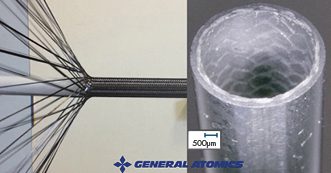
Figure 1. SiGA cladding is a multi-layered composite design composed of SiC fiber in a SiC matrix.
A project is underway to further the development and irradiation testing of a composite silicon carbide matrix as an ATF cladding material. This research is supported through a DOE Funding Opportunity award (DE-FOA-0002308) for the irradiation of a composite silicon-carbide (SiC) ceramic matrix material in an existing U.S. commercial LWR. This work is led by General Atomics – Electromagnetic Systems (GA-EMS) with Structural Integrity Associates (SIA) as a primary subcontractor. For this work, PEGASUS is being adapted to model monolithic and composite SiC manufactured by GA-EMS, SiGA [1], through the incorporation of proprietary material constitutive models. PEGASUS will then be used to provide independent test performance analyses aiding in the design of the irradiation vehicle and predicted material performance. The goal of the testing is to gather irradiation data under prototypic LWR operating conditions and to inform and confirm material performance models for the SiGA-based cladding. A follow-on activity is planned to evaluate the predicted performance compared to data gathered during the post-irradiation examination phase of the project.
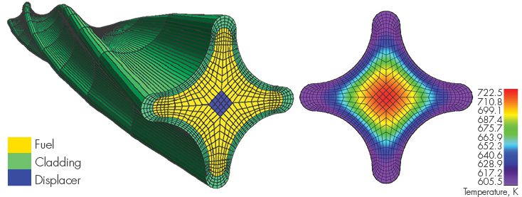
Figure 2. Lightbridge Fuel Design PEGASUS Models
Cruciform Metallic Fuel An additional fuel concept that has been explored using PEGASUS is a cruciform, extruded metallic fuel design proposed by Lightbridge Corporation [2]. This fuel is characterized by a unique multi-lobed fuel cross-section and features a U-50Zr fuel composition. Recent work has been published on fabrication testing of this proposed fuel design by Pacific Northwest National Laboratory (PNNL) [3]. PEGASUS has been used previously to prototype 2D and 3D geometric models and meshes of Lightbridge fuel and to perform fundamental temperature and stress distributions for this fuel under prototypic LWR conditions. PEGASUS has specific modeling tools designed to facilitate “extruded” 3D fuel designs that automate the meshing of these geometries. More work in this area is planned as a proposal has recently been awarded under the DOE NEUP program (DE-FOA-0002732) funding a collaborative project led by Texas A&M University along with Lightbridge, NuScale, and Structural Integrity Associates, Inc. (SI) for modeling this type of fuel for application in a LWR SMR.
URANIUM METAL ALLOY FUELS FOR SODIUM-COOLED FAST REACTORS The initial implementation of metallic alloy fuel and stainless-steel cladding material constitutive models for prototypic fast reactor fuel designs in PEGASUS has been completed. Material properties and behavioral models for U-Pu-Zr fuel and HT-9 (high Chromium, martensitic stainless steel) cladding have been added. Ongoing work includes the implementation of a gaseous swelling and fission gas release behavior model for U-Pu-Zr fuel, a Zr-redistribution model, and a fuel-cladding chemical interaction (FCCI) model that includes the effect on cladding wall thinning.
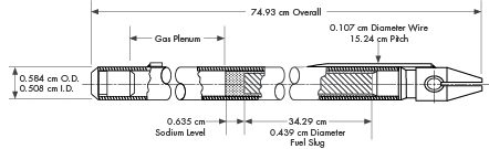
To test the implementation of these models, benchmark tests were prepared that provided comparative data for assessment of the models’ performance. Test cases were chosen from two experimental series irradiated in EBR-II: X430, a 37-pin hexagonal sub-assembly, and X441, a 61-pin bundle. These experiments were designed to test numerous fuel rod design variables and fuel response as a function of fuel alloy composition, smear density, plenum-to-fuel volume ratio, power, and coolant conditions [4]. The general experimental fuel rod design corresponds to the typical driver fuel configuration shown in Figure 3.
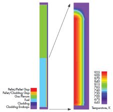
Figure 3. Typical EBR-II Mark-III or Mark-IIIA Fuel Element [5]
Figure 4. Left: 2D Computational Model of Rod DP2, Right: Temperature Contour Plot of the Fuel Stack Region for Rod DP21 at Peak Power (plenum region removed for detail)
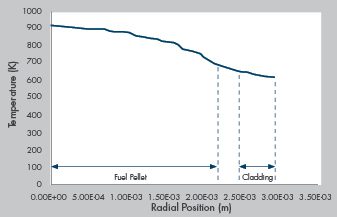
An illustration of the model and selected results from the initial analysis of rod DP21, assembly X441 are shown in the figures above. Figure 4 provides a diagram of the computational model showing the primary components of the model and a plot of the temperature distribution throughout the fueled region of the rod at peak power. Figure 5 provides the radial temperature profile across the fuel rod from the center to the cladding outer surface at peak power near the end of the irradiation period. Temperatures vary from just ~900 K at the pellet center to ~650 K at the cladding surface. The temperature differential is fairly low at ~250 K, as would be expected from a high-conductivity metal fuel rod with a Na-bonded fuel cladding gap. These results are consistent with published experimental observations.
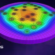
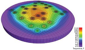
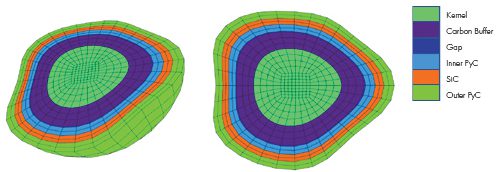
TRISO FUEL MODELING DEVELOPMENT Several advanced fuel material models have been implemented specifically for TRISO fuel in PEGASUS, including thermal and mechanical models for UCO or UO2 kernels, PyC, SiC materials, and a fission gas release model for computing the release of gaseous fission products such as Xe and Kr. In addition to the standard 3D and 2D axisymmetric modeling FEM capabilities in the code, PEGASUS contains several unique tools designed specifically to support TRISO fuel modeling and analysis. These include a “spherical mesh object” tool that can automate the process of generating 2D/3D TRISO spheres, meshing them, and embedding them into a fuel matrix to allow modeling of individual TRISO kernels or fully encapsulated TRISO fuel forms. An example of models generated using the spherical mesh object tool is shown in Figure 6. The spherical mesh object capability is, to our knowledge, unique to PEGASUS and not found in any other fuel performance or general-purpose FEM code. PEGASUS also has a “reshape” function that can automate the process of meshing and modeling deformed TRISO particles to increase user efficiency. Figure 7 illustrates particle meshes that were created using the reshape meshing tool.
These modeling capabilities allow PEGASUS to be used to investigate very detailed mechanical and structural effects in TRISO fuel forms. For example, enabling the detailed analysis of the mechanical interaction between TRISO fuel layers explicitly examining the effects of cracking, debonding, and asphericity within whole or damaged particles.
Figure 5. Radial Temperature Distribution Across the Fuel Rod Model at ~ 486 Days of Irradiation
Planned future development work includes the integration of damage-mechanics modeling and fission product diffusion in the TRISO particle, fuel compact, ad matrix. One failure mode of particular interest that has been identified is cracking of the IPyC layer which propagates through the SiC outer layer. This can create a pathway for enhanced fission product release from the TRISO particle to the surrounding fuel matrix. This failure mechansim appears to occur when the buffer layer remains bonded to the IPyC layer providing the conditions for a synergistic mechanical and chemical failure mechanism that combines cracking, stress concentration, and chemical corrosion (localized Pd-induced corrosion in the SiC [6]. This failure mode is of interest because it can have a strong impact on fuel source term determination for operational TRISO fuel.
Figure 6. Temperature distribution in a cross-section of a 3D slab of a TRISO compact matrix model with a “sparse”, random kernel distribution under prototypic gas-cooled reactor conditions. (Generated using the “spherical mesh object” tool.)
SUMMARY PEGASUS is an advanced analysis tool developed for industry applications that can provide a complimentary and independent capability for nuclear fuel performance. Recent development work on PEGASUS has focused on expanding the applicability of the code to the advanced fuel (ATF) and advanced reactor arena. Future development is planned for PEGASUS that will continue along multiple avenues with an emphasis on advanced fuels and specific thermo-mechanical issues within the industry, such as deterministic failure model development. One example of this is the aforementioned Pd-induced failure mechanism identified for TRISO fuel. SI is actively seeking partners within the advanced fuel community to collaborate with on this work and would welcome inquiries and proposals for expanded application of PEGASUS.
Figure 7. Deformed 3D TRISO particle meshes generated using the “reshape” function tool in PEGASUS.
References
C. P. Deck et al., Overview of General Atomics SiGA™ SiC-SiC Composite Development for Accident Tolerant Fuel, Transactions of the American Nuclear Society, Vol. 120, Minneapolis, Minnesota, June 9–13, 2019.
J. Malone, A. Totemeier, N. Shapiro, and S.Vaidyanathan, Lightbridge Corporation’s Advanced Metallic Fuel, Nuclear Technology, Vol 180, Dec. 2012.
Z. Huber and E. Conte, Casting and Characterization of U-50Zr, PNNL-33873, Pacific Northwest National Laboratory, Richland, Washington 99354, Jan. 2023.
C. E. Lahm, J. F. Koenig, R. G. Pahl, D. L. Porter, and D. C. Crawford, “Experience with Advanced Driver Fuels in EBR-II,” J. Nucl. Mat. 204 (1993) 119-123.
G. L. Hofman, M. C. Billone, J. F. Koenig, J. M. Kramer, J. D. B. Lambert, L. Leibowitz, Y. Orechwa, D. R. Pedersen, D. L. Porter, H. Tsai, and A. E. Wright. Metallic fuels handbook, Technical Report ANL-NSE-3, Argonne National Laboratory, 2019.
J.D Hunn, C.A. Baldwin, T.J. Gerzak, F.C. Montgomery, R.N. Morris, C.M. Silva, P.A Demkowicz, J.M. Harp, and S.A. Ploger, Detection and Analysis of Particles with Failed SiC in AGR-1 Fuel Compacts, Nuclear Engineering and Design, April 2016.
We may request cookies to be set on your device. We use cookies to let us know when you visit our websites, how you interact with us, to enrich your user experience, and to customize your relationship with our website.
Click on the different category headings to find out more. You can also change some of your preferences. Note that blocking some types of cookies may impact your experience on our websites and the services we are able to offer.
Essential Website Cookies
These cookies are strictly necessary to provide you with services available through our website and to use some of its features.
Because these cookies are strictly necessary to deliver the website, refusing them will have impact how our site functions. You always can block or delete cookies by changing your browser settings and force blocking all cookies on this website. But this will always prompt you to accept/refuse cookies when revisiting our site.
We fully respect if you want to refuse cookies but to avoid asking you again and again kindly allow us to store a cookie for that. You are free to opt out any time or opt in for other cookies to get a better experience. If you refuse cookies we will remove all set cookies in our domain.
We provide you with a list of stored cookies on your computer in our domain so you can check what we stored. Due to security reasons we are not able to show or modify cookies from other domains. You can check these in your browser security settings.
Google Analytics Cookies
These cookies collect information that is used either in aggregate form to help us understand how our website is being used or how effective our marketing campaigns are, or to help us customize our website and application for you in order to enhance your experience.
If you do not want that we track your visit to our site you can disable tracking in your browser here:
Other external services
We also use different external services like Google Webfonts, Google Maps, and external Video providers. Since these providers may collect personal data like your IP address we allow you to block them here. Please be aware that this might heavily reduce the functionality and appearance of our site. Changes will take effect once you reload the page.
Google Webfont Settings:
Google Map Settings:
Google reCaptcha Settings:
Vimeo and Youtube video embeds:
Other cookies
The following cookies are also needed - You can choose if you want to allow them:
Privacy Policy
You can read about our cookies and privacy settings in detail on our Privacy Policy Page.
 Structural Integrity Associates, Inc. (SIA) is pleased to announce the appointment of