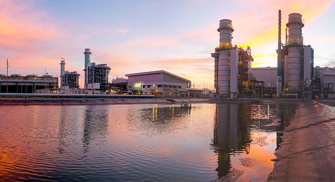
News & Views, Volume 45 | The Importance of HRSG HP Evaporator Tube Internal Deposit Evaluation
By: Barry Dooley
 Evaluation of High Pressure (HP) Evaporator Tube Deposits is important for several reasons:
- Determining if flow-accelerated corrosion (FAC) might be occurring in the lower pressure circuits.
- Regular evaluations can provide information on the internal deposit deposition rate, which is information necessary to help prevent under-deposit corrosion damage mechanisms.
- Provides information necessary to develop an optimized cycle chemistry for HRSGs.
- Can help determine if the HRSG needs to be chemically cleaned.
The leading heat recovery steam generator (HRSG) tube failure mechanisms are FAC, thermal and corrosion fatigue, and under-deposit corrosion (UDC) and pitting. The corrosion products released by the FAC mechanism are transported from the affected area (typically the feedwater or lower pressure systems) and can eventually reach the HP evaporator tubing, so understanding the deposition in the HP evaporator is an important step in determining if FAC might be occurring. Deposition on the inside of HP evaporator tubing is also a precursor to any of the under-deposit corrosion HRSG tube failure mechanisms.

 Grade 91 steel is widely used in tubes, headers and piping of superheaters and reheaters because of its higher strength at elevated temperature compared to low alloy steels such as Grade 22.
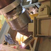
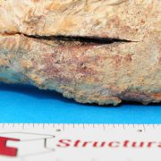
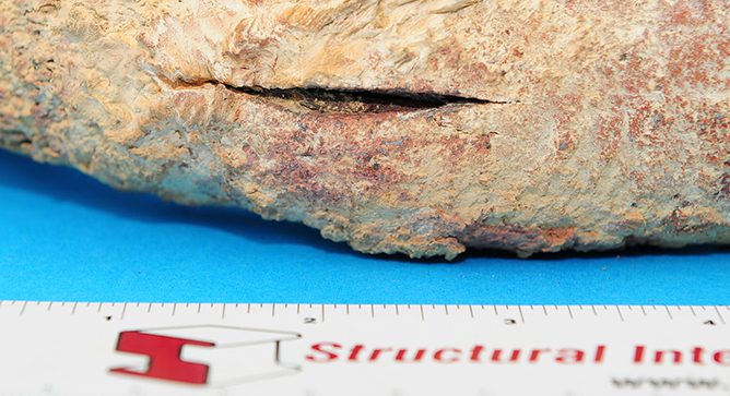
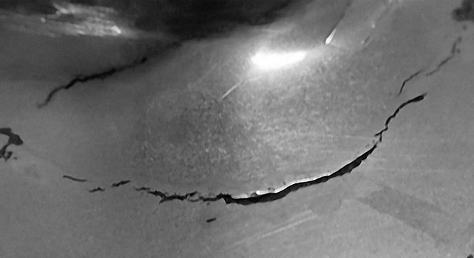
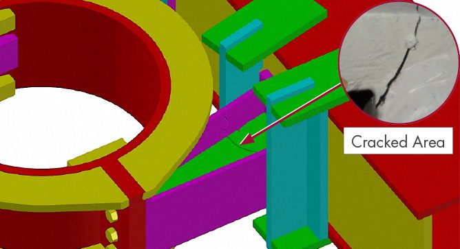
 suction pipe-to-elbow stainless steel weld was identified in both units of a nuclear power plant as depicted in Figure 1.

 Structural Integrity (SI) has significant depth and expertise in current pipeline safety regulations and dedicates substantial resources to ensure a comprehensive understanding of proposed pipeline safety regulations.
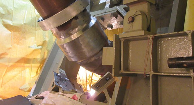
 Determining a course of action once in-service damage is discovered often requires applying a multi-disciplinary approach that utilizes Nondestructive Examination (NDE), analytical techniques such as stress analysis, and metallurgical lab examination.
 Determining a course of action once in-service damage is discovered often requires applying a multi-disciplinary approach that utilizes Nondestructive Examination (NDE), analytical techniques such as stress analysis, and metallurgical lab examination.
 While the 2018 Spring outage season is mostly behind us, we all know a key element in being able to provide safe, reliable, clean and economic power to energy consumers is how successfully plant outages are accomplished.