
News & Views, Volume 44 | Data Driven Solutions for the Most Difficult Problems
By: Andrew Crompton and Mark Jaeger
 In recent years, SI has observed an increasing trend in the use of specialty instrumentation to solve “impossible” problems or answer “indecipherable” questions. This shift was particularly apparent within commercial nuclear, where data-driven solutions have long been perceived as challenging due to short outage windows, personnel dose concerns, and a significant paperwork burden, among other factors. Widespread adoption of instrumentation-based solutions creates new paths to tackling difficult/persistent problems, and shifts the industry focus for critical assets from reactionary to more of a predictive approach. In 2017, SI assisted numerous clients with deployment of specialty instrumentation in this fashion, comprising two general scenarios: 1) new designs/modifications, and 2) repeat failures. Each application requires different sensors and varying analytical methods, but the approach used to leverage the resultant data to solve the problem is generically applicable throughout the energy sector. The text below details important considerations for both scenarios and highlights a successful application of the underlying process for management of thermal fatigue in reactor coolant system branch piping.

 Structural Integrity (SI) has significant depth and expertise in current pipeline safety regulations and dedicates substantial resources to ensure a comprehensive understanding of proposed pipeline safety regulations.
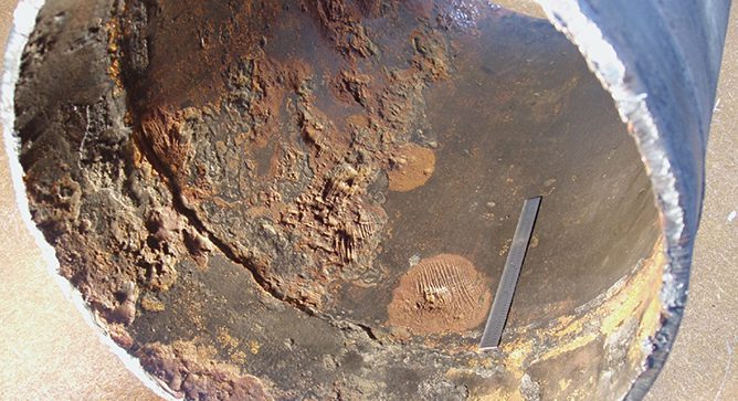
 Determining a course of action once in-service damage is discovered often requires applying a multi-disciplinary approach that utilizes Nondestructive Examination (NDE), analytical techniques such as stress analysis, and metallurgical lab examination.
 Determining a course of action once in-service damage is discovered often requires applying a multi-disciplinary approach that utilizes Nondestructive Examination (NDE), analytical techniques such as stress analysis, and metallurgical lab examination.
 While the 2018 Spring outage season is mostly behind us, we all know a key element in being able to provide safe, reliable, clean and economic power to energy consumers is how successfully plant outages are accomplished.


 A March 16, 2017, advisory bulletin (Docket No. PHMSA-2016-0131 – “Pipeline Safety: Deactivation of Threats”) gave guidance on the deactivation of pipeline threats, including the threat of internal corrosion.
 A dissimilar metal weld (DMW) is created whenever alloys with substantially different chemical compositions are welded together – for example, when a low-alloy steel such as Grade 22 (2¼ Cr-1Mo) is welded to an austenitic stainless steel such as TP304H (18Cr-8Ni).