Soot blower erosion (SBE) is caused by mechanical removal of tube material due to the impingement on the tube wall of particles entrained in the “wet” blower steam. As the erosion becomes more severe, the tube wall thickness is reduced and eventually internal pressure causes the tube rupture.
Mechanism
SBE is due to the loss of tube material caused by the impingement of ash particles entrained in the blowing steam on the tube OD surface.In addition to the direct loss of material by the mechanical erosion, SBE also removes the protective fireside oxide. (Where the erosion only affects the protective oxide layer on the fireside surface, the damage is more properly characterized as erosion-corrosion.) Due to the parabolic nature of the oxidation process, the fireside oxidation rate of the freshly exposed metal is increased. The rate of damage caused by the steam is related to the velocity and physical properties of the ash, the velocity of the particles and the approach or impact angle. While the damage sustained by the tube is a function of its resistance to erosion, its composition, and its operating temperature, the properties of the impinging particles are more influential in determining the rate of wall loss.
Tubing in conventional boilers and heat-recovery steam generators (HRSGs) can be subject to various damage mechanisms.Under-deposit corrosion (UDC) mechanisms have wreaked havoc on conventional units for the past 40-50 years and have similarly worked their way into the more prevalent combined cycle facilities that employ HRSGs.Water chemistry, various operational transients, extended outage periods, etc. all play a detrimental role with regards to damage development (UDC, flow-accelerated corrosion, pitting, etc.).
Fabricated branch connections represent a common industry issue in combined cycle plants. Many are vulnerable to early damage development and have experienced failures.Despite these challenges, a well-engineered approach exists to ensure that the baseline condition is fully documented and a life management plan is put in place to help reduce the overall risk to personnel and to help improve plant reliability.
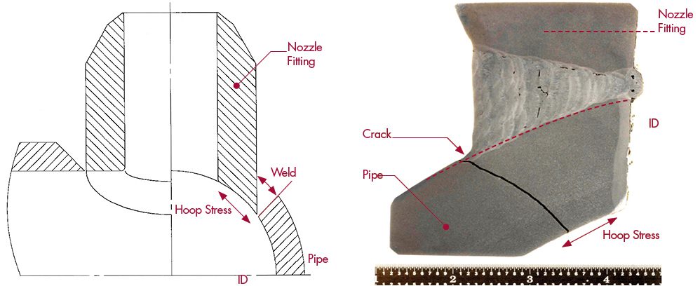
Fabricated branch connections between large bore pipes (including headers and manifolds) are often fabricated with a reinforced branch commonly in the form of a “catalogue” (standard size) fitting, such as an ‘o-let’. These are more prevalent in today’s combined cycle environment as compared to conventional units that used forged blocks or nozzles rather than welded-on, integrally reinforced pipe fittings. The fittings are typically thicker than the pipes in which they are installed to provide compensating reinforcement for the piping run penetration. Full reinforcement is often not achieved as the current Code requirements place all of the reinforcement on the branch side of the weld joint.As a result,higher sustained stresses are generated and, particularly in the case of creep strength enhanced ferritic (CSEF) steels, early formation creep cracking in the weld heat-affected zone (HAZ) can occur (known as Type IV damage – see Figure 1). The well documented challenges of incorrect heat treatment of the o-let weld can also add to the likelihood of damage in CSEF components.Damage is therefore most likely to occur in fabricated branches that operate with temperatures in the creep range.
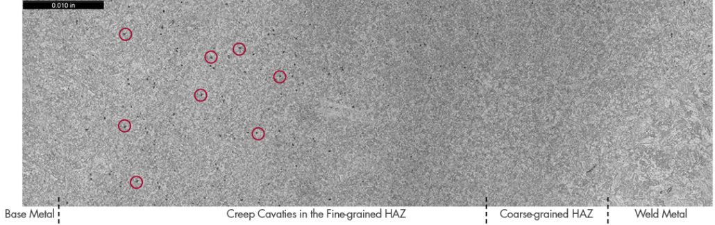
Figure 1. Examples of cavities located within the fine-grained HAZ (a few of the cavities are highlighted in red).
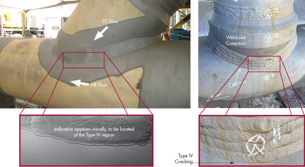
Damage is primarily in the form of creep cracking at the toe of the weld on the main run side of the connection (flank position), as shown in Figure 2. The susceptibility to damage early in life (in some cases, before 50,000 hours of service) has been widely reported. As early as 2008, a warning was issued by an architect engineering (AE) company to advise on the known problems. Despite that warning, use of these fittings with their associated inadequacies remains prevalent.
Figure 2. Example of cracking along the flank positions of o-let connections.
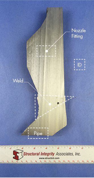
Figure 3. Example of a cross-section through a weld-o-let showing the small size of the weld compared to the thickest part of the nozzle fitting.
Several key factors contribute to early damage development for these components:
Temperature – Most combined cycle plants operate near the 1,040-1,050°F range, which increases the susceptibility to creep damage in Grade 91 HAZs.Some combined cycle plants operate at much lower temperatures (1,005-1,030°F), which can result in a marked increase in the cross-weld strength.
Geometry – Experience has shown that the size of the branch relative to the main run of piping can have a pronounced effect on the damage vulnerability.The larger the opening the more reinforcement that is needed at the weld joint.Current coderequirements place all of the reinforcement on the branch side of the fitting.The amount of required integral reinforcement is defined only by consideration of the crotch location, not the flank location.This is a known limitation of the code which in many cases leaves the flank location with insufficient strength.Figure 3 shows an example of this with a cross-section through a weld-o-let where the small size of the weld compared to the thickest part of the nozzle fitting is evident. SI has performed detailed calculations of these types of cases and found that local stresses at the weld exceeded the allowable stress, even without consideration of weld strength reduction factors (WSRFs).The use of Grade 91 has highlighted this code deficiency both because of the weakness of the fine-grained HAZ in Grade 91 and because of its greater stress sensitivity (higher stress exponent) compared to common low-alloy steels.
Figure 4. Example of ‘set-through’ left and ‘set-on’ right fabricated connection configurations that shows the orientation of the HAZ (red dashed lines) compared to the hoop stress.
It is also important to mention the various styles of welded configurations (Figure 4):
‘Set-on’ represents a more standard o-let connection where the HAZ of the saddle weld follows the OD of the main run pipe and is oriented parallel to the internal hoop stress from pressure.
‘Set-through’ is less common and has mostly been associated with HRSG-supplied piping.In this configuration, the HAZ of the saddle weld traverses through the thickness of the main run pipe and is oriented mostly normal to the internal hoop stress from pressure.
λ This can result in much more rapid damage propagation.
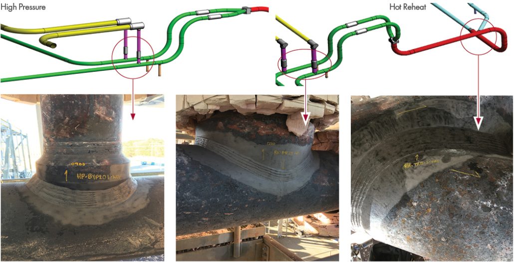
Figure 5. Example of common o-let locations within high energy piping (HEP) systems.
Chemistry – As defined by EPRI, select impurity or tramp elements in high enough concentrations can reduce the damage tolerance of Grade 91 material resulting in greater cavitation susceptibility.
Added System Loads – Damage can become non-uniform and develop more rapidly across the flank positions when malfunctioning supports are in the vicinity of these connections (e.g. bending).
Despite the numerous issues, there are several simple approaches to screen these connections:
Determine the piping systems that operate within the creep regime (typically high pressure/main steam, hot reheat, gas turbine transition cooling, etc.).
Review detailed isometrics on both the architect engineering (AE), HRSG-supplied, and turbine-supplied piping looking for specific junctions (see Figure 5).
Bypass take-offs
HRSG-to-HRSG connection points
Drains
Turbine lead splits
Link piping from HRSG-exit-to-collection manifolds
‘Golden ratio’ of branch OD/main run OD >0.5, where damage susceptibility increases as the ratio approaches 1 – SI has experience with damage development at ratios ≥0.5.
Verify materials of construction.The problem is intensified by the creep-weak nature of the Type IV location (fine-grained HAZ) in Grade 91 steel; however, low-alloy steels such as Grade 11 and Grade 22 are not immune.
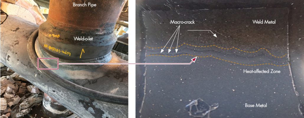
Figure 6. Example of a replication location at a flank position for a weld-o-let. A close-up of the replication site shows a macro-crack (red arrows) located within the Type IV zone (bound by the yellow lines).
If fabricated connections are identified, a baseline condition assessment through nondestructive examinations should be performed via several techniques:
Positive material identification (PMI) via X-ray fluorescence spectrometry (XRF) to assess general material compositions.
Ultrasonic wall thickness testing (UTT) to check thicknesses of the o-let, branch pipe, and main run pipe.
Wet fluorescent magnetic particle testing (WFMT) for identification of surface-connected defects.
Hardness testing of the surrounding area to detect possible anomalies from heat treating.
Metallurgical replication can be used to determine if creep cavities are present and should be performed at the main run pipe side toe at the flank locations on both sides of the connection (Figure 6).
Metal shavings can be collected from the main run of piping for a more detailed chemical analysis to determine if impurities or tramp elements are present at levels that could reduce the overall damage tolerance.
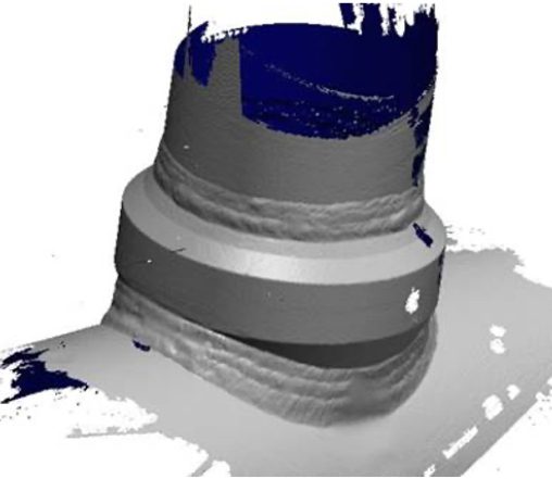
Laser surface profilometry (LSP) is a technique that can be used to capture a detailed 3D model of a component for an accurate geometry for computational modeling.While this technique does not provide any quantitative data itself, it is very useful in analytical techniques to determine potential geometric constraints that could result in additional sustained stresses on the component, which could significantly increase damage accumulation.
Figure 7. Example LSP rendering that can be used for finite element analyses.
Several steps can be considered to mitigate damage in these types of joints:
Weld build-up at the saddle, and in some cases the crown, can be applied to improve the strength of the connection.Finite element analysis, completed via the 3D model captured from the LSP scan (Figure 7), can be used to estimate the amount of weld build-up required to appropriately decrease stresses; however, the amount of weld buildup necessary is very often impractically large.
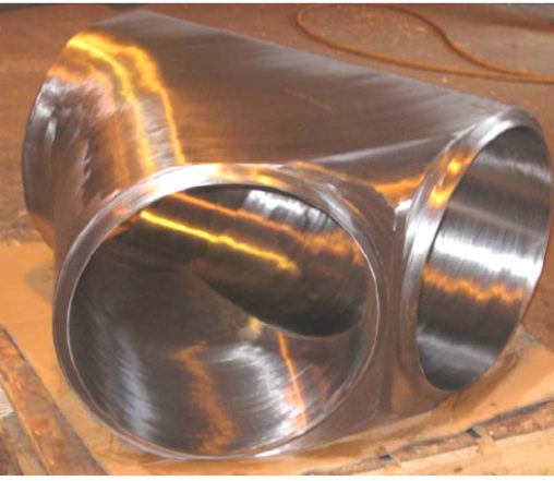
Replacing (or specifying) fabricated joints with forged fittings (Figure 8), which eliminates welding at the branch connection and provides a more balanced reinforcement, is the best method of dealing with these components.
Pipe support modifications to reduce bending and other system loads.
Re-normalizing and tempering the component after fabrication can minimize the detrimental effects of the HAZ and reduce the likelihood of Type IV cracking.
Figure 8. Example of a fully contoured, uniform forging that can eliminate these problematic saddle weld joints.
Summary
In summary, HEP systems should be globally reviewed to determine if these fabricated connections exist and to what level that they may pose a problem for safety and reliability of the plant.Once identified, a baseline condition assessment should be performed, and a life management plan should be implemented.Detailed engineering analyses that use models with the appropriate Grade 91 creep damage mechanics can be used to determine whether these components need true mitigation (repair/replacement) or if appropriate re-inspection intervals are a sufficient mitigation step.Consideration should also be given to assessing continuous operating data (temperatures and pressures) to help understand life consumption with actual operation.
Footnotes
(1) ASME B31.1 (requirements for integrally-reinforced branch fittings defined in Paragraph 127.4.8 and the associated Figure 127.4.8(E).Some requirements for the pressure design of such fittings are also provided in Paragraph 104.3.1 of ASME B31.1.
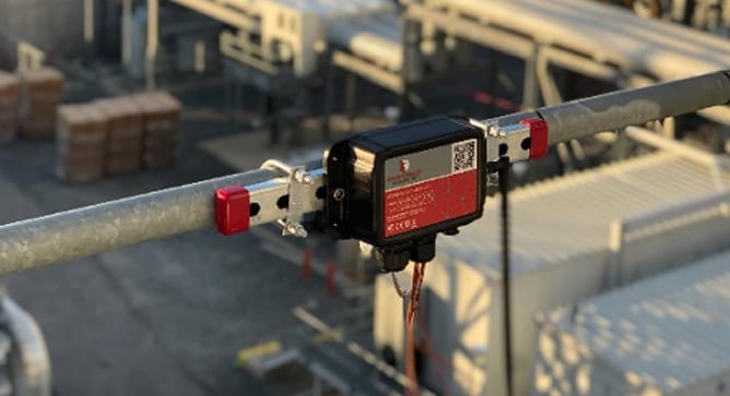
Installed sensors and continuous online monitoring are revolutionizing how power plants manage assets and risk by facilitating the transformation to condition-based maintenance routines. With access to near real-time data, condition assessments, and operating trends, operators have the opportunity to safely and intelligently reduce operations and maintenance costs and outage durations, maximize component lifecycles and uptime, and improve overall operating efficiency.
But not all data is created equal and determining what to monitor, where to monitor, selecting appropriate sensors, and determining data frequency are all critical decisions that impact data value. Furthermore, sensor procurement, installation services, data historian/storage, and data analysis are often provided by separate entities, which can lead to implementation challenges and disruptions to efficient data flow.
https://www.structint.com/wp-content/uploads/2021/05/News-Views-Volume-49-Attemperator-Monitoring-with-Wireless-Sensors-Risk-and-Cost-Reduction-in-Real-Time-1.jpg363668Structural Integrityhttps://www.structint.com/wp-content/uploads/2023/05/logo-name-4-930x191-1.pngStructural Integrity2021-04-20 12:09:442021-07-27 13:15:08News & Views, Volume 49 | Attemperator Monitoring with Wireless Sensors: Risk and Cost Reduction in Real Time
By: Ben Ruchte, Steve Gressler, and Clark McDonald
Properly inspecting plant piping and components for service damage is an integral part of proper asset management.High energy systems constructed in accordance with ASME codes require appropriate inspections that are based on established industry practices, such as implementation of complimentary and non-destructive examination (NDE) methods that are best suited for detecting the types of damage expected within the system.In any instance where NDE is used to target service damage, it is desirable to perform high quality inspections while at the same time optimizing inspection efficiency in light of the need to return the unit to service.This concept is universally applicable to high energy piping, tubing, headers, valves, turbines, and various other power and industrial systems and components.
https://www.structint.com/wp-content/uploads/2021/07/News-View-Volume-47-Surface-Preparation-–-A-Pivotal-Step-in-the-Inspection-Process.jpg363668Structural Integrityhttps://www.structint.com/wp-content/uploads/2023/05/logo-name-4-930x191-1.pngStructural Integrity2020-03-03 16:19:102021-12-15 18:54:49News & View, Volume 47 | Surface Preparation – A Pivotal Step in the Inspection Process
High Energy Piping systems, including main steam and hot reheat piping, are typically very reliable and can often operate trouble-free for decades.However, due to the combination of pressure and temperature at which such systems operate, a failure can have catastrophic consequences from a safety perspective and in terms of equipment loss.Because of this and the requirements of the ASME B31.1 Power Piping code, HEP programs – or as defined by Code, Covered Piping Systems (CPS) – are established to ensure that the integrity of the system is maintained throughout their lifecycle.This article discusses the steps required to implement an HEP / CPS life management program.
A Life Management Program is not synonymous with an inspection program.Inspections are an important part of an overall program but should be complimentary to the use of analytical tools, real-time monitoring, and laboratory examinations
https://www.structint.com/wp-content/uploads/2021/07/News-View-Volume-45-Life-Management-for-High-Energy-Piping-HEP.jpg363668Structural Integrityhttps://www.structint.com/wp-content/uploads/2023/05/logo-name-4-930x191-1.pngStructural Integrity2019-01-01 14:46:312021-07-26 15:29:48News & Views, Volume 45 | Life Management for High Energy Piping (HEP)
We may request cookies to be set on your device. We use cookies to let us know when you visit our websites, how you interact with us, to enrich your user experience, and to customize your relationship with our website.
Click on the different category headings to find out more. You can also change some of your preferences. Note that blocking some types of cookies may impact your experience on our websites and the services we are able to offer.
Essential Website Cookies
These cookies are strictly necessary to provide you with services available through our website and to use some of its features.
Because these cookies are strictly necessary to deliver the website, refusing them will have impact how our site functions. You always can block or delete cookies by changing your browser settings and force blocking all cookies on this website. But this will always prompt you to accept/refuse cookies when revisiting our site.
We fully respect if you want to refuse cookies but to avoid asking you again and again kindly allow us to store a cookie for that. You are free to opt out any time or opt in for other cookies to get a better experience. If you refuse cookies we will remove all set cookies in our domain.
We provide you with a list of stored cookies on your computer in our domain so you can check what we stored. Due to security reasons we are not able to show or modify cookies from other domains. You can check these in your browser security settings.
Google Analytics Cookies
These cookies collect information that is used either in aggregate form to help us understand how our website is being used or how effective our marketing campaigns are, or to help us customize our website and application for you in order to enhance your experience.
If you do not want that we track your visit to our site you can disable tracking in your browser here:
Other external services
We also use different external services like Google Webfonts, Google Maps, and external Video providers. Since these providers may collect personal data like your IP address we allow you to block them here. Please be aware that this might heavily reduce the functionality and appearance of our site. Changes will take effect once you reload the page.
Google Webfont Settings:
Google Map Settings:
Google reCaptcha Settings:
Vimeo and Youtube video embeds:
Other cookies
The following cookies are also needed - You can choose if you want to allow them:
Privacy Policy
You can read about our cookies and privacy settings in detail on our Privacy Policy Page.
 By: Wendy Weiss
 By: Jason Ven Velsor, Roger Royer, and Ben Ruchte
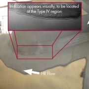

 By: Jason Van Velsor, Matt Freeman and Ben Ruchte

 High Energy Piping systems, including main steam and hot reheat piping, are typically very reliable and can often operate trouble-free for decades.