

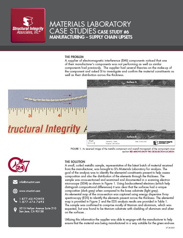
STRAIN-INDUCED PRECIPITATION HARDENING (SIPH) IN AUSTENITIC STAINLESS BOILER TUBES
By: Wendy Weiss
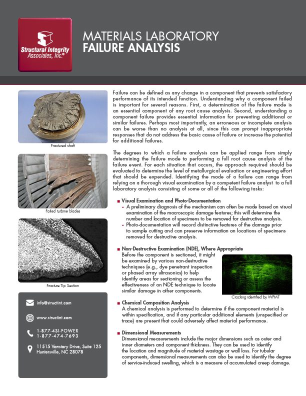
Structural Integrity’s Metallurgical Laboratory offers comprehensive metallurgical laboratory services to support client material issues.
Strain-Induced Precipitation Hardening, also known as SIPH, is a commonly misinterpreted boiler tube failure mechanism that occurs when austenitic stainless steel tubing is cold or warm worked during fabrication and then is installed with either improper or no solution annealing heat treatment. While the basic mechanism and the root cause are understood, the complex interaction between heat chemistry, quantity of cold or warm work, and subsequent thermal history makes it very difficult to predict under precisely what circumstances damage due to SIPH will result in failure of a boiler tube.
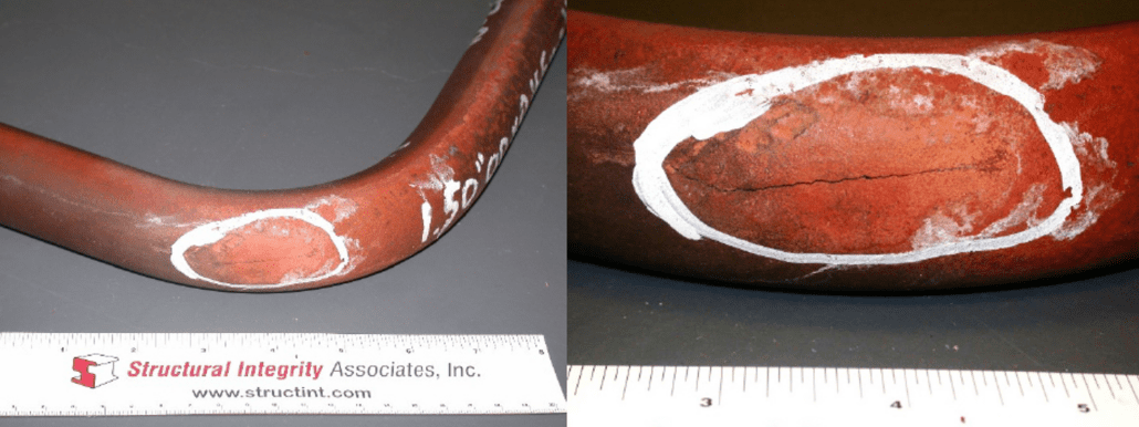
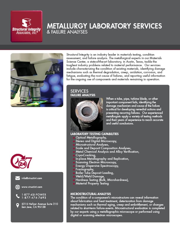
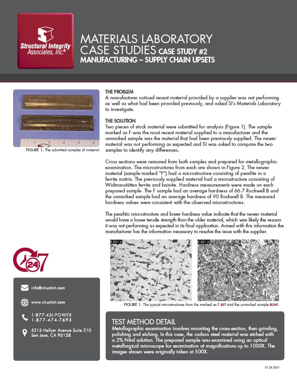
Longitudinally oriented crack at the extrados of a bend in a stainless steel superheater tube.
Mechanism
SIPH occurs when a heat of austenitic stainless steel containing certain precipitate-forming elements (e.g., niobium, titanium, vanadium, etc.) either intentionally or as residuals is cold or warm worked during subsequent material processing. The cold or warm working creates excess defects in the sub-structure of the material, which serve as preferred sites for precipitation of temper-resistant carbides or carbo-nitrides. Precipitation occurs when the material is heated to a sufficiently high temperature that is well below the solution annealing temperature. This can occur rapidly during a poorly executed heat treatment if the material does not reach the proper solution annealing temperature, or it can occur more slowly at typical operating temperatures for superheater or reheater tubing in utility-type boilers.
Once formed, precipitates anchor to the defects, resulting in a substantial increase in the elevated temperature or creep strength of the interior of the grains. At the same time, there is a narrow zone of material immediately adjoining the grain boundaries that remains largely precipitate-free due to the diffusional characteristics of the grain boundary itself. Ultimately, the interior portion of the individual grains becomes very strong at elevated temperatures while the material immediately adjoining the grain boundaries becomes comparatively creep weak. In addition, any surface-active elements that may be present in the material, such as arsenic, tin, antimony, etc., will tend to concentrate at the grain boundaries, further reducing their strength.
Regardless of when the precipitation occurs, once the interior of the grains has been strengthened, the grain boundary regions are weakened. Any strain imposed on the material in response to an applied or residual stress is forced to concentrate in the grain boundary region, which substantially magnifies its effect. For example, suppose the bulk strain experienced by a cold-worked stainless superheater tube segment is very small – a fraction of a percent – and the material has undergone the SIPH reaction. The strengthened grain interiors will undergo no strain. Conversely, within the much smaller volume of the comparatively weak grain boundaries, the accumulated strain will be orders of magnitude higher than the bulk level.
Typical Locations
Features
Root Causes
The single root cause of SIPH is the failure to properly solution anneal susceptible heats of austenitic stainless steel tubing that has been either cold or warm worked during fabrication.
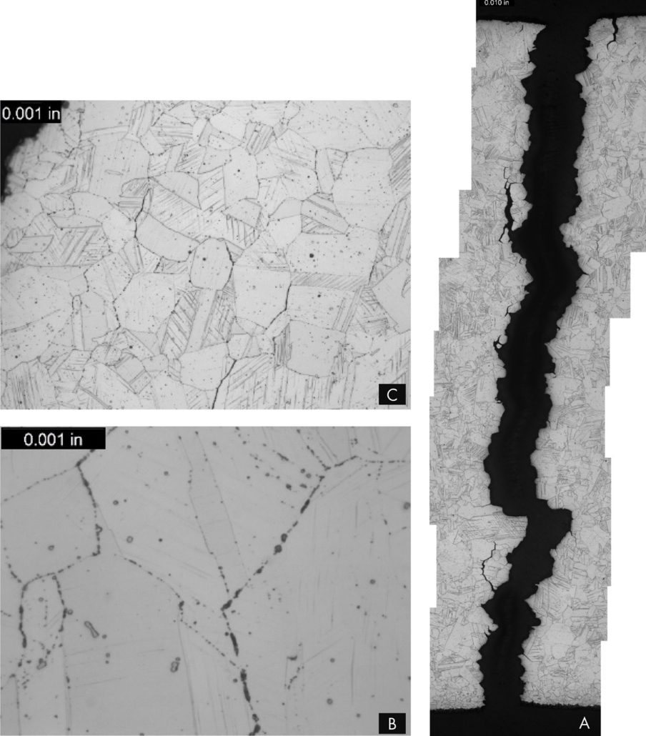
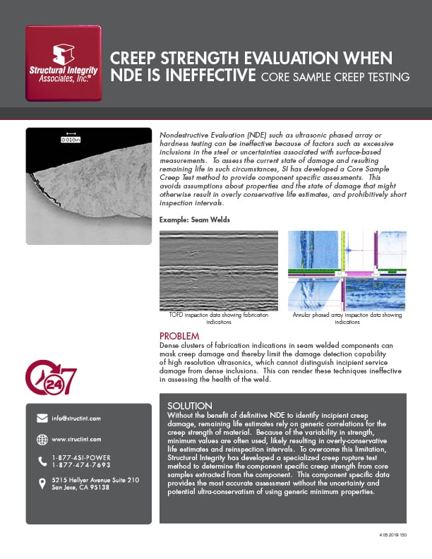
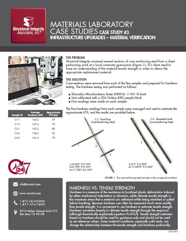
An overall, cross-sectional view of the intergranular crack (image A) with higher magnification views of some of the secondary grain boundary microfissures and voids (image C). Slip bands (parallel lines in image B) indicate local deformation.
For any situation involving material property characterization, Structural Integrity has an experienced group of materials specialists and a full-service metallurgical testing laboratory that can help.
SEE THESE OTHER RELATED MATERIALS FROM THE SIA METALLURGICAL LABORATORY


By: Terry Totemeier
A client recently ordered a Type 316 stainless steel pipe coupling fitting for use in a high-pressure, high-temperature steam line operating at 1005°F. The fitting that was received was so-called dual grade Type 316/316L stainless steel. Given the limitations on using “L” grades of stainless steel at high temperatures, the client requested that SI perform a serviceability assessment for the fitting to determine if it could be safely used until the next scheduled outage when a replacement non-L grade fitting would be available.
 BACKGROUND
The fitting ordered was a ½” nominal diameter (NPS ½), 6000# (Class 6000) full coupling socket-welding fitting in accordance with the ASME B16.11 specification, material ASME SA-182 forging, Type 316 stainless steel (designated as F316 in SA-182). The fitting supplied was dual grade F316/316L material with a carbon content of 0.023% per the material test certificate. The designation of this material as “dual grade” means that it meets the requirements of both F316 and F316L material grades. This is possible because the chemical composition requirements of these two grades overlap, with the primary difference between them being carbon content. For F316 the carbon content is specified to be 0.08% maximum (no minimum), while for F316L the carbon content is specified to be 0.030% maximum. Therefore, material with carbon content less than 0.030% will meet the requirements for both grades. It is worth noting that the carbon content of “H” grade of 316 stainless steel (F316H per SA-182) is specified to be 0.04-0.10%. The H grade is intended for use at high temperatures.
The received fitting was installed in a main steam valve pressure equalizing line with a steam temperature/pressure of 2750 psia/1015°F at design conditions and 2520 psia/1005°F at operating conditions. The fitting was welded to Grade P11 pipe on one side and Grade P22 pipe on the other side. The applicable code was stated to be ASME BPVC Section I.
With a reported carbon content of less than 0.04%, the fitting is technically not permitted for use in ASME Section I construction above a temperature of 1000°F. Per the ASME Boiler and Pressure Vessel Code (BPVC) Section II, Part D, Table 1A, the allowable stresses for SA-182, F316 material are valid at or above 1000°F only when the carbon content is greater than 0.04% (Note G12). Per the same table, SA-182, F316L material is only permitted for use in Section I construction up to 850°F. The reason for this temperature limitation is that the long-term creep-rupture strength of Type 316 stainless steel with lower carbon content is reduced compared to material with higher carbon content because fewer carbides form during service to strengthen the grain boundaries. There are no other adverse impacts of the lower carbon content, e.g., on fatigue strength or oxidation resistance.
The short-term serviceability of the fitting with low carbon content was assessed by comparing bounding pressure stresses in the fitting with the reported creep-rupture strength for Type 316L material. Per the ASME B16.11 specification, Class 6000 socket-welding fittings are compatible with NPS Schedule 160 pipe, meaning that pressure stresses in the fitting will be less than those in Sch 160 pipe with minimum wall thickness according to ASME B36.10 (pipe dimension specification), in other words, the fitting will be at least as strong as the pipe.
ASSESSMENT
The dimensions of NPS ½, Schedule 160 pipe per the ASME B36.10 pipe specification are 0.84” outer diameter (OD), 0.165” minimum wall thickness (MWT). For an operating steam pressure of 2,520 psi, the reference hoop stress per the equation in ASME BPVC Section I, Appendix A-317 is 5.05 ksi. Per the general design guidance in ASME B16.11 (Section 2.1.1) the pressure stresses in the fitting must be less than this.
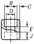
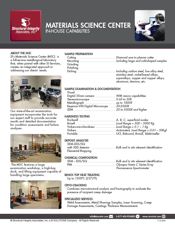
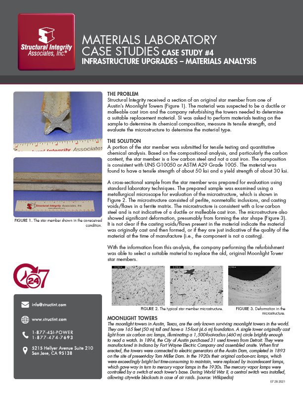
Figure 1. Schematic diagram for a socket-welding coupling fitting. Per ASME B16.11, an NPS ½, Class 6000 fitting has relevant dimensions B = 0.875” maximum, C = 0.204” minimum, and D = 0.434” minimum.
Since the fitting in question is cylindrical, comparative hoop stresses can also be calculated from dimensions given in ASME B16.11, although these may not be exact due to the varied wall thickness in the fitting. According to Table I-1 of ASME B16.11, the central body of the fitting is 1.283” OD and 0.395” MWT (Figure 1). The reference hoop stress calculated using the A-317 equation at 2,520 psi stream pressure and these dimensions is 2.63 ksi, considerably less than 5.05 ksi. In the female socket ends of the fitting, the OD is also 1.283”, but the minimum wall thickness is 0.204”, leading to a calculated reference hoop pressure stress of 6.58 ksi. Note that the actual stresses in the socket ends will be much less than this because the pipe will be inserted and welded into the socket, taking up the pressure loading, but the calculated stress can be taken as a bounding value.
Creep-rupture strengths for Type 316L stainless steel have been reported in ASTM Data Series DS 5S2 publication, “An Evaluation of the Yield, Tensile, Creep, and Rupture Strengths of Wrought 304, 316, 321, and 347 Stainless Steels at Elevated Temperatures” (ASTM, 1969). According to Table 7 in this report, the average 10,000 hour creep-rupture strengths for Type 316L at 1000°F and 1050°F are 34.5 and 25 ksi, respectively. Minimum creep-rupture strengths are typically taken as 80% of the average strength, so the inferred minimum strengths at 1000°F and 1050°F are 27.6 and 20 ksi, respectively.
The reported 10,000 hour creep-rupture strengths in the temperature range of interest are more than twice the calculated bounding pressure stresses in the fitting, so it was judged that there is very little risk of failure of the fitting by creep-rupture in the next 10,000 hours of service.
This result is unsurprising since the 1005°F is barely into the creep range for Type 316 regardless of carbon content. The carbon content effects become more pronounced at higher temperatures (approximately 1100°F and above).
CONCLUSION
Based on the above assessment, it was SI’s opinion that the Type 316L fitting with carbon content less than 0.03% was suitable for a limited period of service (less than 10,000 hours) until it can be replaced. Given that the fitting is reportedly welded to low-alloy steel pipe on either side, SI also recommended that a Grade 22 (2.25Cr-1Mo) low-alloy steel fitting be considered as a replacement, which would eliminate dissimilar metal welds (DMWs) between the fitting and pipes. DMWs are prone to premature failure due to thermal fatigue, weld fusion line cracking, and decarburization of the ferritic material. This voluntary recommendation made by SI, was not part of the original scope of work, but may have been just as critical a finding as it shed light upon a failure risk previously unknown by the client.
SIGN UP FOR OUR NEWSLETTER
*Join the conversation. Sign up to receive emails, events, and latest information!
1-877-4SI-POWER
(1-877-474-7693)


