News & Views, Volume 46 | In-line Inspection Performance Validation Pipe Experiment
By: Jacob Arroyo
 You’ve just completed the first in-line inspection (ILI) of a new pipeline asset. The ILI tool results are in, and there are no required repairs! However, how sure are we of the accuracy of the results? Could the tool have under-called some of the reported anomalies? Are there any regulatory requirements beyond the “response criteria” mentioned in CFR 192 and 195 for operators of hazardous transmission pipelines? These are the problems that ILI verification is trying to solve.
Traditionally, validations can be done using costly excavations of anomalies found by the tool. In cases where those anomalies need to be repaired, this approach is effective, and the validation does not require any further excavations. For some ILI inspections, the tool does not call any anomalies that need to be repaired. The traditional approach, in this case, has been to excavate sub-critical anomalies just for validation. In such cases, an ILI validation spool can be a valuable asset. ILI validation spools can be designed to quantify the uncertainty of the full spectrum of anomaly types without additional excavations, thus freeing up valuable resources to be allocated elsewhere to improve safety, minimizing the exposure risk of excavating pipeline assets while under full operating pressure.
 Longitudinal seam-welded hot-reheat steam piping operating in the creep regime is a continuing life-management challenge for many older fossil-fired power plants.
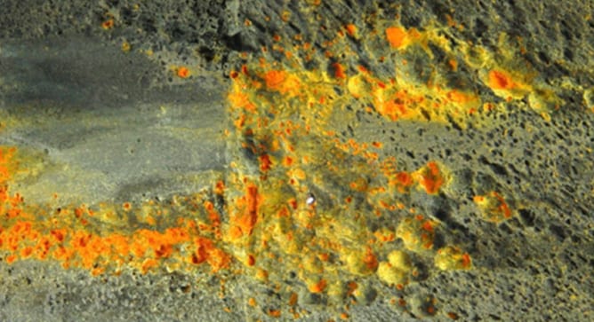
 Recently, a client approached SI after finding a through-wall flaw in an autoclave at the head-to-shell weld as indicated by a visible dye liquid penetrant examination (Figure 1). The autoclave was one of eight similar vessels used for processing the client’s product. Three of the autoclaves are identical in construction to the flawed autoclave and operate with similar process conditions. Remote visual examination by the client indicated that all four autoclaves had similar observations at the inside of the head-to-shell weld, but only one was leaking. The remaining four autoclaves are smaller and are used infrequently. The initial call from the client was for SI to provide emergent support for inspection of the three autoclaves identical to the leaking one to meet production demands. SI responded quickly and examined all four autoclaves using a manual phased array ultra-sonic technique (PAUT) from the exterior of the vessel. The manual PAUT examination provided excellent coverage of the weld region and visualization of the through wall flaw (Figure 2).
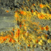
 Structural Integrity recently had the opportunity to support a client’s emergent needs when their Standby Service Water (SSW) piping system experienced a pinhole leak just downstream of a valve. Concerned about other locations in the piping system with similar configurations, the site asked SI to assist with the expedited development of assessment and disposition plans for these other components. In response, SI was able to lean on our core competencies in failure analysis, advanced NDE inspection, and flaw evaluation to develop and deploy a comprehensive solution that met our client’s expedited timeline and helped them to mitigate the threat of future unplanned outages. The following sections outline how SI utilized our in-depth knowledge, cutting-edge technology, and world-class engineering to meet our client’s needs.
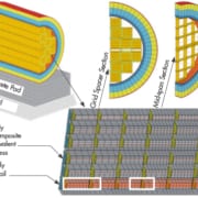
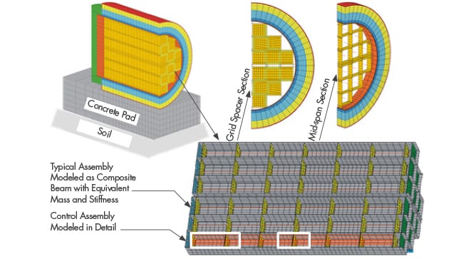 Structural Integrity Associates is participating in a Department of Energy (DOE) Integrated Research Projects (IRP) program focused on storage and transportation of used nuclear fuel (UNF). The project, entitled Cask Mis-Loads Evaluation Techniques, was awarded to a university-based research team in 2016 under the DOE Nuclear Fuels Storage and Transportation (NFST) project. The team is led by the University of Houston (U of H) and includes representatives from the University
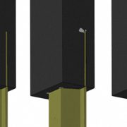
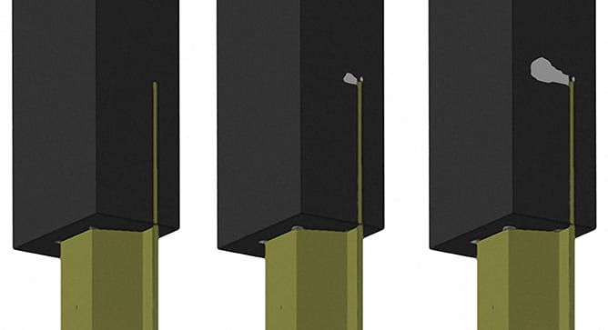 In 2018, Structural Integrity Associates, Inc. (SI) supported the United States Army Corp of Engineers (USACE) in the structural assessment of the concrete-to-steel connection in typical I-Section flood walls. A representative flood wall section is shown in Figure 1. This effort was part of a broader scope of work in which the USACE is revising their guidance for the design of flood and retaining walls, EM 1110-2-6066.
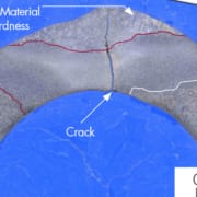
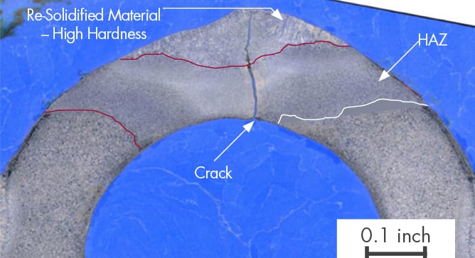 Grade 23 is a creep strength enhanced ferritic (CSEF) steel that was designed to offer similar creep strength to Grade 91 but with lower Cr content and, in the original concept, fabrication without pre- and post-weld heat treatment making the material attractive for the furnace wall tubes of ultra-supercritical coal plants where T12 has insufficient strength and T91 would be too complex to fabricate. Experience gained with T23 has shown that pre-heat is necessary and that post-weld heat treatment should also be performed when the material is employed in “high restraint” applications such as furnace wall tubes. Like other CSEF steels, T23 is very sensitive to heat treatment, and care must be taken to ensure that hard, brittle microstructures do not enter service – particularly in high restraint applications such as furnace wall tubes.
 TRU Compliance, a division of Structural Integrity Associates, announced in March the achievement of accreditation from the International Accreditation Service (IAS) as a product certification body for seismic, wind, and blast/physical security performance of nonstructural components. According to the International Accreditation Service, TRU Compliance is the second company to be certified for Seismic performance of non-structural components and the first company to be certified for Wind and Blast/Physical Security performance.
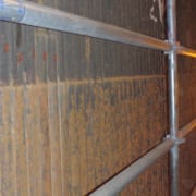
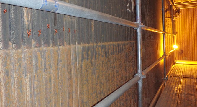 Industry experience shows that waterwall tubing in conventional boilers can be susceptible to fireside corrosion, depending on fuel type, firing practice, etc. In boilers where fireside corrosion has been identified as a maintenance issue, wastage rates of 5 to 25 mils/year are not uncommon. Since the mid 1990s, the installation of low NOx burner systems designed to lower NOx emissions has significantly increased the wastage rates in some boilers. Operators of subcritical boilers have reported wastage rates as high as 30 mils/year, while those operating supercritical boilers have reported rates exceeding 100 mils/year in the worst cases. These higher damage rates have resulted in an increase in tube failures, and operators have struggled to accurately define the extent of the damage and install the appropriate mitigating technologies.